
Table of contents: Disassembly ↓ Assembly ↓
Disassembly
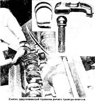
Loosen the valve drive clearance adjusting bolts as much as possible so that the valve drive levers can be removed.
Remove the lever retaining springs and the levers themselves (see photo).
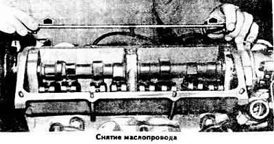
Remove the oil line.
Remove the camshaft from the cylinder head supports.
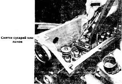
Compress the valve springs with a special device, release the valves from the crackers and remove the valves.
Remove the springs with plates.
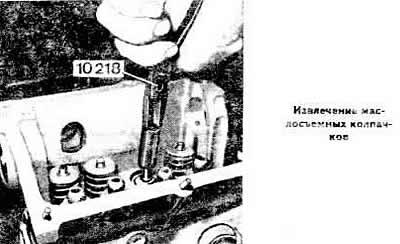
Remove the valve stem oil seals and spring support washers using pliers 10 218.
If the removed parts do not need to be replaced, arrange them in order so that they can be installed in their original place during assembly.
Wash all removed parts with gasoline or trichloroethylene.
Check the degree of wear of the valve guide bushings (for dimensions, see subsection "Design and technical characteristics").
Measure the clearance between the valve stem and the guide bushing using a stand with an indicator. To do this, insert a new valve into the guide bushing so that its stem is level with the edge of the bushing. Place the indicator leg on the valve head and measure the clearance.
If the clearance exceeds the maximum allowable clearance, equal to 1.0 mm for intake valves and 1.3 mm for exhaust valves, replace the cylinder head, since replacement of the guide bushings is not allowed and they are not supplied as spare parts.
Using a ruler, check the non-flatness of the mating surface of the cylinder head (it is best to perform this operation on a surface plate) and sand it if necessary.
Check the condition of the valve springs and valves.
Check the condition of the valve seats and grind them if necessary. Grinding should be carried out only with the help of special equipment and in compliance with the dimensions specified in the subsection "Design and technical characteristics".
If necessary, grind the working chamfers of the inlet valves. The working chamfers of the outlet valves cannot be ground. Wiping the outlet valves is allowed, in other cases they must be replaced.
Before assembly, thoroughly clean the cylinder head.
Assembly
Install the valve spring support washers in place, insert the valves into the guide bushings, having first lightly lubricated the valve stems with engine oil.
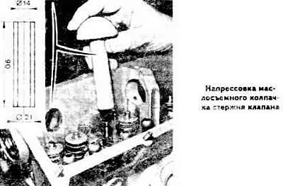
Use the VW 10 204 mandrel to press new valve stem seals onto the guide bushings. To do this, press the valve stem seal into the mandrel hole, press hard on the head of the tool and press the valve stem seal onto the valve stem until it stops. After removing the mandrel, check that the seal is installed correctly.
Install the valve springs and spring retainers. Install the crackers using a valve spring compressor.
Lubricate the bearing journals and camshaft cams with engine oil and install it together with the oil seal.
Install the levers onto the adjusting bolts.
Install the retaining levers by inserting them into the grooves of the adjusting bolts so that the springs rest on the levers.
Note: If the threads on the adjusting bolt bushing are damaged, a Helo-Coli or SEDC type threaded insert bushing can be used.
Using mandrel 10 203, press in the camshaft oil seal.
Install the camshaft toothed pulley and tighten its mounting bolt to a torque of 8 kgf·m.
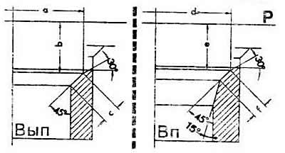
Dimensions for grinding valve seats:
Vp-intake valve seat;
Vyp — exhaust valve seat;
P — mating surface of the cylinder head;
a and d — outer diameter of the working chamfer of the valve seat;
b and e — recess of the working chamfer and valve seat;
c and f are the width of the working chamfer of the valve seat.
(Information obtained from this resource: AUDImanual)