Table of contents: Checking cylinder diameters ↓ Checking the clearances between the… ↓ Checking the axial clearance of the… ↓ Checking the dimensions of pistons… ↓
Checking cylinder diameters
Make precise measurements of the cylinder diameters. Measurements should be made with a bore gauge in three zones both in the transverse direction "A" and in the longitudinal direction "B", as shown in the diagram in the section "Engines models EP, YP, YZ, DS, OT and DZ".
In cases where wear exceeds the permissible values by more than 0.08 mm, bore the cylinders to the nearest repair size and install pistons of the corresponding repair size.
Checking the clearances between the bearings and the crankshaft journals
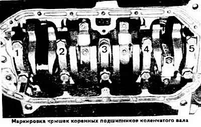
Install the crankshaft into the cylinder block.
Thoroughly clean the working surfaces of the bearings and the corresponding crankshaft journal. Place a piece of calibrated plastic wire equal in width to the bearing on the surface of the journal.
Depending on the type of journal being checked, install the connecting rod with cover or the main bearing cover on the journal and tighten the nuts or mounting bolts accordingly. Tighten the connecting rod bolt nuts first to a torque of 3.0 kgf·m, then turn 90° further, or the main bearing cap mounting bolts to a torque of 6.5 kgf·m. Do not allow the engine crankshaft to turn.
Carefully remove the lid and use the scale on the package to determine the gap size by flattening the wire. More detailed information is provided in the accompanying documentation from the manufacturer of the calibrated wire.
The nominal design gap is 0.030-0.080 mm (maximum permissible 0.17 mm) for root and 0.020-0.076 mm (maximum permissible 0.095 mm) for connecting rod journals.
If the gap is greater than the maximum, then replace the liners on these journals with new ones. If the crankshaft journals are changed and ground to the repair size, then replace the liners with repair ones (increased thickness).
Checking the axial clearance of the crankshaft
Check the axial clearance of the crankshaft using a feeler gauge on the third support, which should be no more than 0.20 mm.
If the clearance is greater than the limit, and the crankshaft main journal is not ground, then to ensure the required axial movement of the shaft, inserts with thrust flanges of the nominal size should be placed on the third support. If the main journals of the shaft are ground to the repair size, then for this purpose it is necessary to place inserts of the corresponding repair size on the third support.
Checking the dimensions of pistons and piston rings
Determine the degree of piston wear by measuring the diameter 15 mm from the edge of the piston skirt perpendicular to the axis of the piston pin (see photo in section "Engines of the EP, YP, YZ, DT, DS and DZ models"). The piston must be replaced if its diameter differs by more than 0.04 mm from the permissible values (see subsection "Design and technical characteristics").
Replace piston rings or pistons if the clearances between piston rings and grooves exceed the maximum permissible values for wear (see subsection "Design and technical characteristics").