
Troubleshooting the Brake System Indicator
When the ignition is turned on, the brake system indicator flashes to check the operation, when the engine is running it should go out, if it flashes longer or flashes while driving, you should immediately check the brake fluid level. Perhaps there was a depressurization and failure of one brake circuit, which can be noticed by the increased free travel of the pedal.
Indicator check: see the text "Indicator check" in the section "Troubleshooting the Coolant Indicator".
If the indicator flashes when the engine is running, despite the fact that the brake fluid level in the reservoir is above the "min" mark, try disconnecting the plug from the brake fluid reservoir level sensor.
If the light goes out, it means the sensor in the tank is faulty - replace the tank.
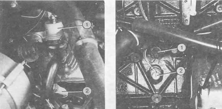
Location of hydraulic switches:
Left: In the 4-cylinder engine, the 0.3 bar hydraulic switch is located on top of the oil filter flange (1) (here, instead of a switch, a switch and a sensor are installed together). At the bottom of the oil filter flange there is a switch with a 1.8 bar hydraulic drive (2).
Right: On a 5-cylinder engine, the hydraulically operated 0.3 bar (1) and 1.8 bar (2) switches are located on the left side of the engine.
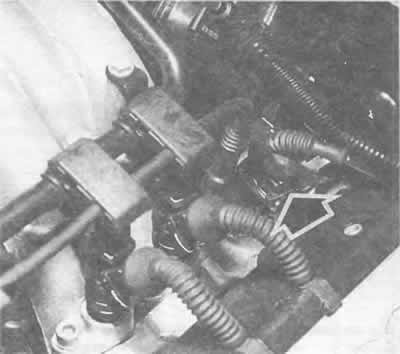
This plug connection (arrow), located at the rear of the left cylinder head, contains all the wires to the oil temperature sensor, oil pressure sensor and both hydraulic switches.
[The original publication in its entirety is posted on the website: audimanual.ru]