
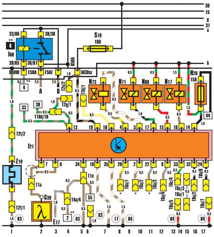
- A - battery;
- D - ignition switch;
- E17 - ignition interlock switch and reversing light switch;
- G39 - lambda probe (2341) (2342);
- J21 - fuel injection control unit;
- J60 - Automatic transmission relay;
- N17 - starting injector (4443);
- N71 - Idle speed stabilization valve (4431);
- N73 - pressure regulator (4341);
- N80 - Solenoid valve 1 for the gasoline vapor recovery device (4343);
- S19 - fuse in the fuse box;
- S28 - fuse for KE III-Jetronic control unit;
- T1a - 1-pin connector on the left in the engine compartment;
- T1e - 1-pin connector (black) behind the instrument panel;
- T2f - 2-pin connector on the left in the engine compartment;
- T2x - 2-pin connector (black) behind the instrument panel (diagnostic);
- T2u - 2-pin connector (brown) behind the dashboard;
- T3d - 3-pin connector (black) behind the instrument panel;
- T4a - 4-pin connector behind the instrument panel;
- T6a - 6-pin connector behind the instrument panel;
- T6c - 6-pin connector behind the instrument panel;
- T8a - 8-pin connector (black) behind the instrument panel (encoding);
- T10d - 10-pin connector (yellow) behind the instrument panel;
- Z19 - Lambda probe heating
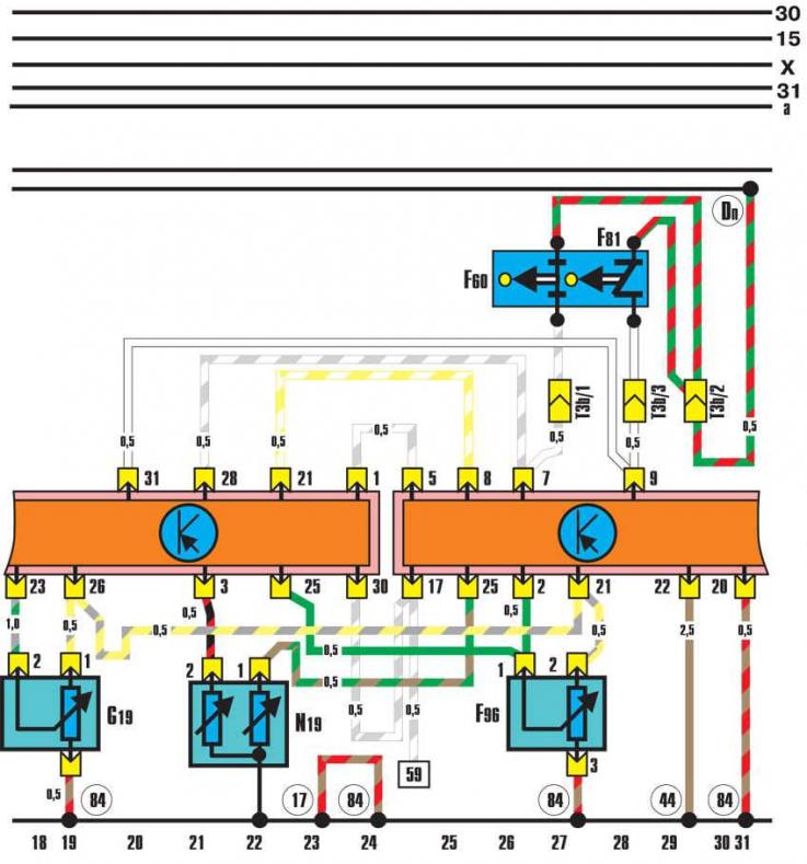
- F60 - Idle switch (2121);
- F81 - Full Load Switch (2123);
- F96 - height sensor (2223);
- G19 - air flow meter potentiometer (2232);
- J21 - fuel injection control unit;
- J154 - Electronic ignition system control unit;
- N19 - temperature sensor;
- T3d - 3-pin connector (black) on the left in the engine compartment;
- 17 - ground point on the intake manifold;
- 44 - ground point at the bottom left on the front body pillar;
- 84 - connection to engine ground in the front wiring harness on the right;
- D11 - "positive" connection (15) via fuse 28 in the front wiring harness on the right
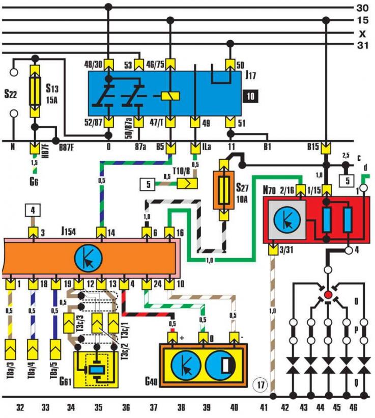
- G6 - fuel pump;
- G40 - Hall sensor (2113);
- G61 - knock sensor (2142);
- J17 - Fuel pump relay (4433);
- J154 - Electronic ignition system control unit;
- N - ignition coil;
- N70 - ignition coil with power output stage;
- O - ignition distributor;
- P - spark plug tip;
- Q - spark plug;
- S13 - fuse in the fuse box;
- S22 - fuse in the fuse box;
- S27 - control unit fuse;
- T3c - 3-pin connector (black) on the left in the engine compartment;
- T8a - 8-pin connector (black) behind the instrument panel (encoding);
- T10 - 10-pin connector (blue) behind the instrument panel;
- 17 - ground point on the intake manifold;
- D9 - "positive" connection (15) via fuse 24 in the front wiring harness on the right
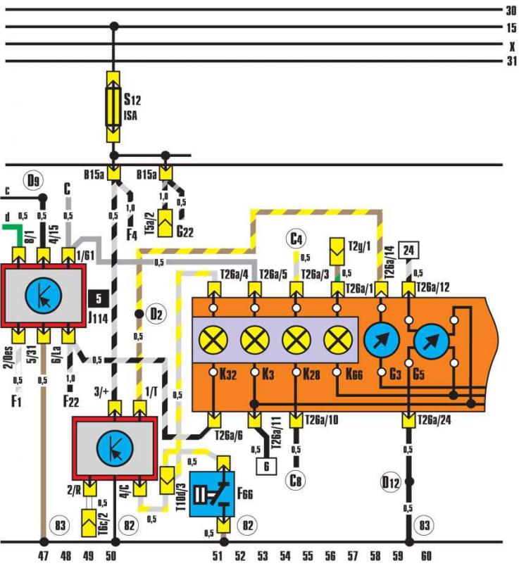
- C - generator;
- F1 - oil pressure sensor (0.18 MPa);
- F4 - Reverse light switch;
- F22 - oil pressure sensor (0.03 MPa) (3114);
- F66 - coolant level sensor;
- F76 - electronic thermal switch;
- G3 - coolant temperature gauge;
- G5 - tachometer sensor;
- G22 - speedometer sensor;
- J114 - Oil pressure control unit;
- K3 - oil pressure indicator lamp;
- K26 - coolant temperature and level indicator lamp;
- K32 - brake lining wear indicator lamp;
- K66 - ignition control lamp;
- S12 - fuse in the fuse box;
- T2u - 2-pin connector (brown) behind the dashboard (diagnostic);
- T5a - 5-pin connector (brown) behind the dashboard;
- T6c - 6-pin connector (black) behind the instrument panel;
- T10d - 10-pin connector (yellow) behind the instrument panel;
- T26a - 26-pin connector (brown) in the instrument panel;
- 82 - ground connection 1 in the front left wiring harness;
- 83 - connection to ground 1 in the wiring harness;
- C4 - connection in the front wiring harness on the left;
- C8 - connection in the front wiring harness on the left (brake pad wear indicator);
- D2 - connection in the front wiring harness on the right (temperature sensor);
- D9 - "positive" connection (15) via fuse 24 in the front wiring harness on the right