
Repair Chevrolet Repair Toyota Repair Honda Repair AvtoVAZ Repair Mercedes-Benz Repair BMW Repair Opel
Home  |  Contacts  |  Sitemap  |    
English Русский
Български
Беларускі
Український
Српски
Hrvatski
Română
Polski
Slovenský
Magyar
AudiManual.ru


  • AUDI 80
  • AUDI 100
  • AUDI A3
  • AUDI A4
  • AUDI A6
  • AUDI A8
  • AUDI Q
  • OTHER
  • ARTICLES
C4 (1990-1994) C4 (1990-1994, petrol) C3 (1982-1990) C3 (1982-1990, petrol) C3 (1982-1990, diesel)

Instrument panel, coolant temperature sensor (Audi 100 C3)

  • Home
  • Audi 100
  • C3 (1982-1990)
  • Electrical equipment
  • Electrical circuits
  • Instrument panel, coolant temperature sensor
            0
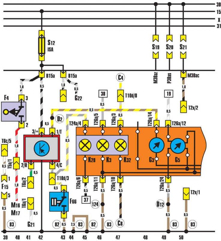
Instrument panel, coolant temperature sensor
  • F4 - Reverse light switch;
  • F15 - gearbox switch;
  • F66 - Coolant Temperature Gauge Sensor;
  • F76 - electronic thermal switch;
  • G3 - coolant temperature indicator;
  • G5 - tachometer;
  • G21 - speedometer;
  • G22 - speedometer sensor;
  • K3 - oil pressure indicator lamp;
  • K28 - coolant temperature and level indicator lamp;
  • K32 - brake pad wear indicator lamp;
  • M16 - left reversing light bulb;
  • M17 - Right reversing light bulb;
  • S12 - fuse in the fuse box;
  • S19 - fuse in the fuse box;
  • S20 - fuse in the fuse box;
  • S21 - fuse in the fuse box;
  • T2x - 2-pin diagnostic connector (black) behind the instrument panel;
  • T5a - 5-pin connector (brown) behind the dashboard;
  • T6a - 6-pin connector (black) behind the instrument panel;
  • T10d - 10-pin connector (yellow) behind the instrument panel;
  • T26a - 26-pin connector (brown) instrument panels;
  • 32 - ground point on the left behind the instrument panel;
  • 82 - ground connection 1 in the front left wiring harness;
  • 83 - ground connection 1 in the front wiring harness on the right;
  • 124 - connection to "ground" in the wiring harness on the left in the engine compartment;
  • C4 - connection in the front wiring harness on the left;
  • C8 - connection in the front wiring harness (brake pad wear indicator);
  • D2 - connection in the front wiring harness on the right (temperature sensor);
  • D12 - connection in the front wiring harness on the left


This article was copied from an online resource: audimanual.ru
The article was checked by auto expert Daniil Ushakov
This article is available at russian, bulgarian, belarusian, ukrainian, serbian, croatian, romanian, polish, slovak, hungarian

Share information:
Previous articles
Audi 100 C3: Electrical circuits
Next articles

Ignition system, oil pressure control device
Fuel injection with controlled knock combustion
KE-Jetronic injection device
Interior trunk lighting
KE III-Jetronic injection system (100 kW engine)
Battery, starter, generator (diesel engine)
Glow plugs, glow plug relay
Oil pressure monitoring device


Similar articles on other Audi car models:
Electrical diagram of the instrument panel, voltage stabilizer,… Audi 80 B4 (1991-1996)
Instrument cluster unit, combi-processor in the instrument… Audi A3 Type 8L (1996-2003)
Cooling system — coolant pipes, coolant temperature sensor,… Audi A4 B8 (2007-2015)
Electrical diagram of the Motronic control unit, valve… Audi A6 C5 (1997-2004)
Instrument panel Audi A8 D2 (1994-2002)
Removal the temperature sensor fan on the instrument panel «V42» Audi Q5 Type 8R (2008-2017)
Removal and installation coolant temperature sensor G62 Audi A2 (1999-2005)
Link to this page in different formats


Visitor comments

No comments yet


How much will 26 + 50 =


100(C4, 1990-1994) 
  • General information
  • User manual
  • Power unit
  • Engine repair
  • Ignition system
  • Fuel system (gasoline)
  • Fuel system (diesel)
  • Lubrication system
  • Cooling system
  • Exhaust system
  • Transmission
  • Clutch
  • Car gearbox
  • Drive shafts
  • Chassis
  • Car suspension
  • Steering
  • Wheels and tires
  • Brake system
  • Body
  • Ventilation and heating
  • Body repair
  • Electrical equipment
  • Power devices
  • Lighting and appliances
  • Electrical circuits
 
100(C4, 1990-1994, petrol) 
  • General information
  • Operation and maintenance
  • Power unit
  • Engine repair
  • Exhaust system
  • Cooling system
  • Supply system
  • Air filter
  • Mono-Motronic injection system
  • Digifant injection system
  • KE-III-Jetronic and KE-Motronic
  • MPI and MPFI injection system
  • Transmission
  • Clutch
  • Car gearbox
  • Chassis
  • Suspension and steering
  • Brake system
  • Wheels and tires
  • Body
  • Exterior
  • Interior
  • Electrical equipment
  • Fuses and relays
  • Power devices
  • Ignition system
  • Lighting and signaling
  • Equipment and devices
  • Electrical circuits
 
100(C3, 1982-1990) 
  • General information
  • User manual
  • Maintenance
  • Specifications
  • Power unit
  • Engines 4-cylinder
  • Engines 5-cylinder
  • Diesel engine
  • Cooling system
  • Power system (carburetor)
  • Power system (injector)
  • Fuel system (diesel)
  • Transistor ignition system
  • Electronic ignition system
  • Transmission
  • Clutch
  • 4 speed gearbox 014
  • 5 speed gearbox 013 and 093
  • 5 speed gearbox 016 and 012
  • Shift mechanism KP 016
  • Automatic transmission
  • Front wheel drive
  • Chassis
  • Front suspension
  • Rear suspension
  • Steering
  • Brake system
  • Body
  • Body elements
  • Electrical equipment
  • Lighting and appliances
  • Power devices
  • Electrical circuits
 
100(C3, 1982-1990, petrol) 
  • General information
  • Maintenance and operation
  • 4 cylinder engine
  • Engine repair
  • Cooling and lubrication system
  • Supply system
  • Ignition system
  • 5 cylinder engine
  • Engine repair
  • Cooling and lubrication system
  • Supply system
  • Ignition system
  • Transmission
  • Clutch and drive shafts
  • 4 speed gearbox 014
  • 5 speed gearbox 013 and 093
  • 5 speed gearbox 016 and 012
  • Automatic gearbox
  • Chassis
  • Steering
  • Front suspension
  • Rear suspension
  • Brake system
  • Body
  • Body elements
  • Doors, locks and windows
  • Body repair
  • Electrical equipment
  • Equipment and devices
  • Power devices
  • Electrical circuits
 
100(C3, 1982-1990, diesel) 
  • General information
  • User manual
  • Maintenance
  • Troubleshooting
  • Power unit
  • Engine in a car
  • Engine removed
  • Cooling system
  • Fuel system
  • Exhaust system
  • Starting and charging
  • Preheating
  • Transmission
  • Clutch
  • Mechanical gearbox
  • Automatic gearbox
  • Drive shafts
  • Chassis
  • Brake system
  • Suspension
  • Steering
  • Body
  • Exterior
  • Interior
  • Electrical equipment
  • Equipment and devices
  • Electrical circuits
 
AudiManual.ru © 2017-2026 · Mobile version · Feedback · Sitemap: EN BG BY UA RS HR RO PL SK HU · Site search · News and articles
80 B2 · 80 B3 petrol · 80 B3 · 80 B4 · 100 C3 diesel · 100 C3 petrol · 100 C3 · 100 C4 petrol · 100 C4 · A3 Type 8L · A4 B5 petrol · A4 B5 · A4 B6 petrol · A4 B6 · A4 B7 · A4 B8 · A6 C4 · A6 C5 · A6 C5 Allroad · A8 D2 · Q5 Type 8R · Q7 Typ 4L · Audi A2 ·
This site uses cookies 🍪. Click the button to accept this fact.