
Table of contents: Control unit - removal and… ↓ Control switch - removal and… ↓
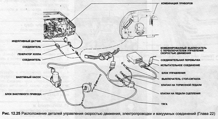
The speed control system automatically maintains the desired speed when activated at speeds above 35 km/h. The system controls the throttle position via a vacuum drive unit and maintains a constant speed. The vacuum drive unit is controlled by an electronic control unit, which in turn receives information from various sensors. The system can be switched off by the driver via a switch or whenever the clutch or brake pedal is pressed.
Control unit - removal and installation
1. Disconnect the negative battery cable.
2. Remove the trim under the dashboard on the driver's side.
3. Disconnect the electrical wiring, unscrew the mounting screws and remove the control unit.
4. Installation is carried out in reverse order.
Control switch - removal and installation
5. Control switch - part of the steering column combination switch, the removal and installation procedure is contained in Chapter 5.
Clutch/Brake Pedal Valves
6. Disconnect the negative battery cable.
7. Remove the trim panel or package shelf, as necessary, to gain access to the clutch and brake pedals.
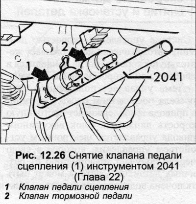
8. Disconnect the electrical wiring and vacuum hose from the appropriate valve, then remove the unit from the holder. There is a special Audi 2041 tool for removing the valves, but even with the special tool, the valves must be discarded after removal, as this will damage the threads.
9. To install new valves, place them into the holders as far as possible.
10. Raise the clutch or brake pedal as far as possible to set the valve adjustment.
11. Install the trim, connect the battery.
Vacuum drive - removal and installation
12. Disconnect the throttle linkage on the vacuum actuator unit.
13. Disconnect the vacuum hose.
14. Unscrew the lock nut and remove the vacuum drive unit.
15. Installation is carried out in reverse order.
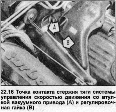
16. To adjust the tie rod, check the clearance at the point where the tie rod contacts the vacuum actuator bushing with the throttle at rest (photo). The clearance should be 0.1-1.0 mm. If necessary, adjust the fastening nut in the center of the tie rod.
Vacuum pump - removal and installation
17. Remove the screws securing the expansion tank of the cooling system and move the tank to the side.
18. Disconnect the vacuum hoses and electrical connector, then remove the screws and remove the pump.
19. Installation is carried out in reverse order.
[The original article is available on the website: AUDIMANUAL.RU]