Repair Chevrolet Repair Toyota Repair Honda Repair AvtoVAZ Repair Mercedes-Benz Repair BMW Repair Opel
Home  |  Contacts  |  Sitemap  |    
English Русский
Български
Беларускі
Український
Српски
Hrvatski
Română
Polski
Slovenský
Magyar
AudiManual.ru


  • AUDI 80
  • AUDI 100
  • AUDI A3
  • AUDI A4
  • AUDI A6
  • AUDI A8
  • AUDI Q
  • OTHER
  • ARTICLES
B8 (2007-2015) B7 (2004-2008) B6 (2000-2006) B6 (2000-2006, petrol) B5 (1994-2001) B5 (1994-2001, petrol)

Front brake disc — inspection, removal and installation (Audi A4 B5)

  • Home
  • Audi A4
  • B5 (1994-2001)
  • Chassis
  • Brake system
  • Front brake disc — inspection, removal and installation
            0
Table of contents: Examination ↓ Removal ↓ Installation ↓
Note: Before you begin, please read the warnings at the beginning paragraph 4, about the harmfulness of asbestos dust.


Examination


Note: To maintain uniformity and braking efficiency, both discs are replaced if at least one requires replacement. At the same time, the brake pads are also replaced with new ones.


1. Place chocks under the rear wheels, apply the handbrake and raise the front of the car. Install safety stands. Remove the corresponding wheel. When removing the wheels, tighten one bolt into each hub to prevent the brake discs from shifting relative to the hub. If necessary, use washers or old large nuts.

2. If you need to increase visibility, remove the brake pads. Turn the disc and check the depth of the grooves and potholes. Small potholes "have a right to be", but excessive ones indicate the need for replacement.

3. A common occurrence is the formation of a rusty crown around the perimeter of the disc, it can be removed if necessary. Check the top tire of the disc with a micrometer. Take measurements in several places. If at least one place the thickness of the disc has decreased less than the permissible Specifications, both disks must be replaced.

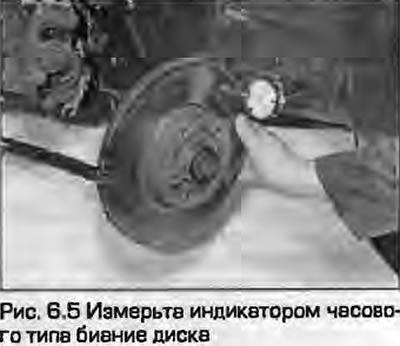
4. If there is a suspicion that the disc is bent, use a dial indicator or a ruler with a set of feeler gauges to check the disc runout and compare it with the tolerances given in Specifications. To take measurements, secure the disc with at least two wheel mounting bolts, using flat washers to ensure the disc sits correctly on the hub.


5. Measurements should be taken approximately 10 mm from the outer edge of the disc. Measure the runout at several radii of the disc. If the disc runout exceeds the permissible limit, remove the disc and make sure that the mating surface of the disc and the hub is absolutely clean. If the runout exceeds the permissible limit, the disc must be replaced. But first check the condition of the hub - see. chapter 10.

5. Measurements should be taken approximately 10 mm from the outer edge of the disc. Measure the…


6. Check for disc cracks (especially around the wheel mounting bolts). Replace the disk if necessary.

Removal


7. Unscrew the two bolts securing the caliper to the steering knuckle and remove the caliper. Tie the caliper to the suspension strut with a piece of wire so as not to put stress on the brake hose. If necessary, the bracket for mounting the caliper can be removed by unscrewing the mounting bolts as described in paragraph 8.

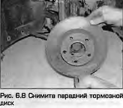
8. If the disc is to be installed backwards, mark its position relative to the hub with paint or chalk. Unscrew the bolts that secure the disc to the hub, screwed in when checking the disc, and remove the disc. If the disc is not seated properly, help it come off with a rubberized hammer.


8. If the disc is to be installed backwards, mark its position relative to the hub with paint or…


Installation


9. Installation is the reverse procedure of removal. Please note the following:
  • a) The mating surfaces of the disc and hub must be clean and smooth.
  • b) If present, align the previously applied marks.
  • c) If installing a new disc, use a suitable solvent to remove the protective grease from the disc before installing it on the hub.
  • d) Before installation, clean the caliper mounting bolts, place the bracket on the pads and tighten the mounting bolts to the specified torque.
  • d) Install the wheel and lower the car. Tighten the wheel mounting bolts to the specified torque. Finally, press the brake pedal several times to allow the pads to approach the disc and take up working position.
The article was checked by auto expert Timur Bazhenov
This article is available at russian, bulgarian, belarusian, ukrainian, serbian, croatian, romanian, polish, slovak, hungarian

Share information:
Previous articles
Audi A4 B5: Brake system
Next articles

Rear brake pads — replacement
Front brake pads — replacement
Hydraulic tubes and hoses — replacement
Hydraulic system — bleeding
Rear brake disc — inspection, removal and installation
Front Brake Caliper — Removal, Repair and Installation
Rear Brake Caliper — Removal, Repair and Installation
Master Brake Cylinder — Removal, Repair and Installation


Similar articles on other Audi car models:
Front brake pads — inspection, removal and installation Audi 80 B3 (1986-1991, petrol)
Front brake disc — removal and installation Audi 100 C3 (1982-1990, diesel)
Removal and installation the brake disc / caliper Audi A3 Type 8L (1996-2003)
Front Brake Pads with Caliper FNR-G60 — Removal and Installation Audi A6 C5 Allroad (1999-2005)
Removal and installation the engine Audi A8 D2 (1994-2002)
Removal and installation the front final drive Audi Q7 Typ 4L (2005-2015, diesel)
Brake mechanism with floating caliper, front brake disc Audi A2 (1999-2005)
Link to this page in different formats


Visitor comments

No comments yet


How much will 35 + 47 =


A4(B8, 2007-2015) 
  • General information
  • Operating instructions
  • Power unit
  • Petrol engines 1.8 l
  • Petrol engines 1.8/2.0 l
  • Petrol engines 3.0 l
  • Petrol engines 3.2 l
  • Fuel system (petrol)
  • Diesel engines 2.0 l (CA*)
  • Diesel engines 2.0 l (CJCB)
  • Diesel engines 2.7/3.0 l
  • Diesel engines 3.0 l
  • Fuel system (diesel)
  • Transmission
  • Manual gearbox 0B1
  • Manual gearbox 0B2
  • Manual gearbox 0B3
  • Manual gearbox 0B4
  • Automatic transmission 0B5
  • Automatic transmission 0B6
  • Automatic transmission 0AW
  • All-wheel drive system
  • Chassis
  • Front suspension
  • Rear suspension
  • Brake system
  • Steering system
  • Body
  • Exterior
  • Interior
  • Seats
  • Doors, locks and windows
  • Security system
  • Heating and air conditioning
  • Electrical equipment
  • Audio system
  • Power devices
  • Equipment and devices
  • Lighting and lamps
  • Electrical circuits
 
A4(B7, 2004-2008) 
  • General information
  • Introduction to manual
  • Troubleshooting
  • Operating instructions
  • Maintenance
  • Power unit
  • Petrol engines 2.0 (ALT)
  • Petrol engines 2.0 (TFSI)
  • Petrol engines 1.8 (MPI)
  • Diesel engines
  • Cooling system
  • Air conditioner
  • Fuel and exhaust system
  • Ignition system
  • Starting and charging
  • Transmission
  • Clutch
  • Manual gearbox
  • Automatic gearbox
  • Drive shafts
  • Chassis
  • Brake system
  • Front suspension
  • Rear suspension
  • Steering
  • Body
  • Exterior
  • Interior
  • Electrical equipment
  • Equipment and devices
  • Lighting and signaling
  • Windscreen wipers and washers
  • Electrical diagrams
  • Electrical diagrams (since 2007)
 
A4(B6, 2000-2006) 
  • General information
  • Vehicle Description
  • User manual
  • Maintenance
  • Power unit
  • Gasoline engine
  • Diesel engine
  • Lubrication system
  • Cooling system
  • Supply system
  • Injection system
  • Exhaust system
  • Ignition and control
  • Transmission
  • Gear box
  • Clutch and drive shafts
  • Chassis
  • Brake system
  • Car suspension
  • Steering
  • Body
  • Heating and ventilation
  • Exterior (external elements)
  • Interior (internal elements)
  • Electrical equipment
  • Power devices
  • Lighting and appliances
  • Electrical circuits
 
A4(B6, 2000-2006, petrol) 
  • General information
  • Introduction to the guide
  • Car care
  • Power unit
  • Engine repair
  • Lubrication system
  • Cooling system
  • Injection and control system
  • Ignition system
  • Power and exhaust system
  • Transmission
  • Clutch and drive shafts
  • Car gearbox
  • Chassis
  • Suspension and wheels
  • Steering
  • Brake system
  • Body
  • Interior
  • Exterior
  • Electrical equipment
  • Equipment and devices
  • Lighting and signaling
  • Power devices
  • Electrical circuits
 
A4(B5, 1994-2001) 
  • General information
  • Introduction to the guide
  • Car care
  • Maintenance (gasoline)
  • Maintenance (diesel)
  • Power unit
  • Gasoline engines
  • Diesel engines
  • Engine overhaul
  • Cooling system
  • Fuel injection (gasoline)
  • Fuel system (diesel)
  • Exhaust system
  • Ignition system
  • Transmission
  • Clutch
  • Mechanical gearbox
  • Automatic gearbox
  • Drive shafts
  • Chassis
  • Brake system
  • Car suspension
  • Steering
  • Body
  • Exterior
  • Interior
  • Doors, locks and windows
  • Heating and ventilation
  • Electrical equipment
  • Power devices
  • Equipment and devices
  • Electrical circuits
 
A4(B5, 1994-2001, petrol) 
  • General information
  • Vehicle description
  • Maintenance
  • Power unit
  • Engine repair
  • Turbocharging
  • Exhaust system
  • Cooling system
  • Ignition system
  • Fuel system
  • Motronic injection system
  • MPI and MPFI injection system
  • Transmission
  • Clutch
  • Gearbox and shafts
  • Chassis
  • Steering
  • Car suspension
  • Brake system
  • Wheels and tires
  • Body
  • Heating and ventilation
  • Body parts
  • Electrical equipment
  • Fuses and relays
  • Power devices
  • Lighting and lamps
  • Tools and devices
  • Electrical circuits
 
AudiManual.ru © 2017-2026 · Mobile version · Feedback · Sitemap: EN BG BY UA RS HR RO PL SK HU · Site search · News and articles
80 B2 · 80 B3 petrol · 80 B3 · 80 B4 · 100 C3 diesel · 100 C3 petrol · 100 C3 · 100 C4 petrol · 100 C4 · A3 Type 8L · A4 B5 petrol · A4 B5 · A4 B6 petrol · A4 B6 · A4 B7 · A4 B8 · A6 C4 · A6 C5 · A6 C5 Allroad · A8 D2 · Q5 Type 8R · Q7 Typ 4L · Audi A2 ·
This site uses cookies 🍪. Click the button to accept this fact.