
Table of contents: ATE/Teves calipers ↓ Lucas Calipers ↓ All models ↓ ATE/Teves calipers ↓ Lucas Calipers ↓ All models ↓
Warning! Replace the entire set of brake pads at once, not the axle - never replace the pads on just one wheel, as this may result in uneven braking of the wheels. Keep in mind that the dust formed by the wear of brake pads containing asbestos is carcinogenic. Never use compressed air to clean the brakes, do not inhale the dust. Wear a protective mask when working with the brakes. DO NOT USE gasoline-based solvents to clean brake system parts - use brake cleaner or methyl alcohol.
1. Apply the handbrake. Raise the front of the car and install safety supports. Then remove the front wheels. When removing the wheels, tighten one bolt into each hub so that the brake discs do not move relative to the hub.
ATE/Teves calipers
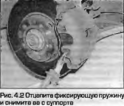
2. Carefully remove the spring that holds the pads (Fig. 4.2).
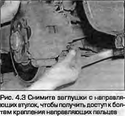
3. Remove the plugs from the guide bushings to gain access to the guide pin mounting bolts (Fig. 4.3).
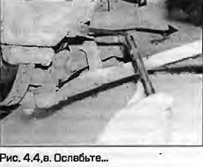
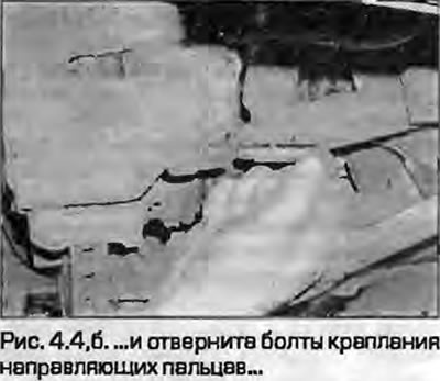
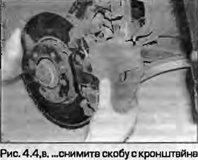
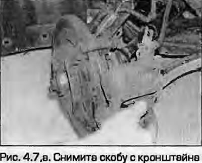
4. Unscrew the upper and lower mounting bolts of the guide struts, remove the bracket from the pads and tie it to the suspension strut with a piece of wire so as not to load the brake hose (fig. 4.4, a-c).
 |
 |
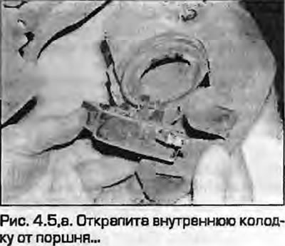
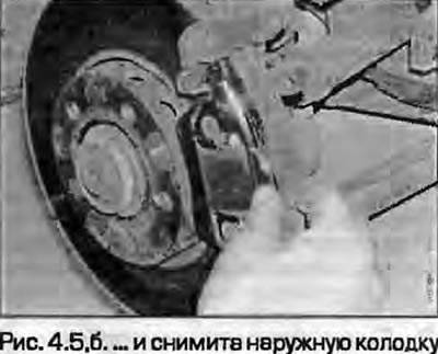
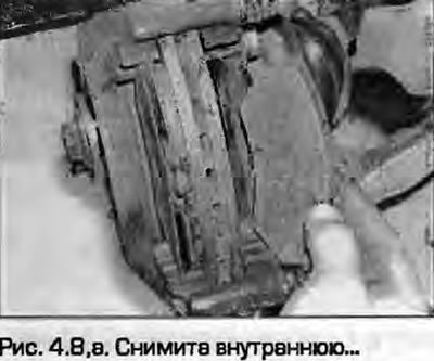
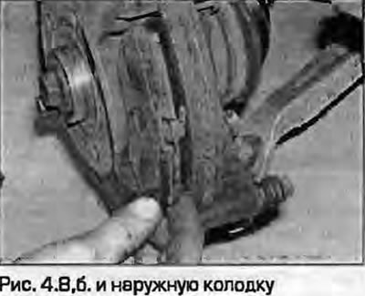
5. Unclip the inner pad from the caliper piston and remove the outer pad (fig. 4.5, a, b).
 |
 |
Lucas Calipers
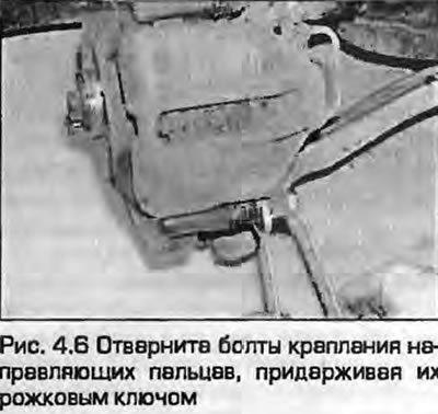
6. Loosen the upper and lower guide pin mounting bolts, holding them with an open-end wrench (Fig. 4.6). New bolts will be required for installation.
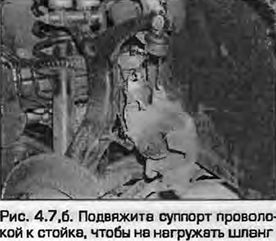
7. Remove the caliper from the mounting bracket. Tie the caliper to the stand with wire so as not to put stress on the brake hose (fig. 4.7, a, b).
 |
 |
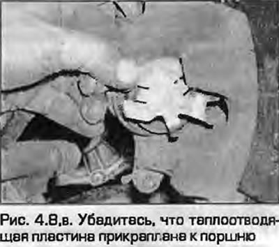
8. Remove the pads. Make sure that the heat-dissipating plate remains secured to the end of the piston (fig. 4.8, a-c).
 |
 |
All models
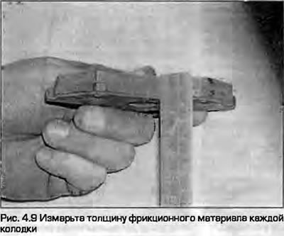
9. First measure the thickness of the friction material (Fig. 4.9). If any pad is damaged or has unacceptable wear (see Specification), replace the entire set of pads to avoid upsetting the brake balance. The pads should also be replaced if any of them are oily - there is no satisfactory way to remove oil from the friction material without changing its structure. If any of the pads are oily, find the cause and eliminate it before installing a new set of pads.
10. If the pads look good, carefully clean them from dirt with a soft wire brush, paying special attention to the back and sides. Clean the grooves in the friction material, remove foreign inclusions. Clean the seats in the caliper and bracket.
ATE/Teves calipers
11. The guide pins should slide easily on the caliper bushings. Make sure the rubber boots on the guides are not damaged. Brush off any dust from the caliper and piston, but do not inhale it, as it is hazardous to your health. The dust boots around the pistons should be secure, and the pistons should be free of corrosion, leaks, or other damage. If any of these components require attention - see paragraph 8.
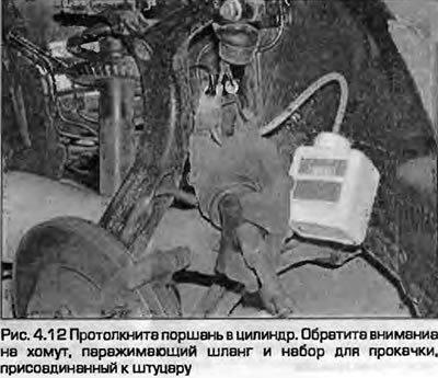
12. If you are installing new pads, the piston must be pressed into the caliper flush with its surface. To do this, you can use a clamp or use wooden blocks as levers. Clamp the brake hose, and when the cylinder is compressed, open the bleed nipple, attaching a hose dipped in a can to it so that the old fluid does not return to the system (Fig. 4.12).
Note: The ABS system is sensitive to the cleanliness of the brake fluid - the slightest dirt can block its operation. Use the above method to bleed the brakes - and the fluid will be renewed more often.
13. Secure the inner pad to the piston and install the outer pad with the friction material facing the disc. The outer pad has an arrow stamped on the outer edge indicating the normal direction of rotation of the brake disc. When installing new pads, remove the transport foil (if any) and remove any traces of adhesive.
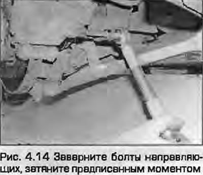
14. Install the bracket in place and insert the guide mounting bolts, tightening them to the specified torque (Fig. 4.14).
15. Install the plugs on the guide bushings and attach the wear sensor wiring to the lower cap.
16. Install the brake shoe retaining spring. Press the inner edge of the spring so that its ends are securely fixed to the surface of the shoes.
Lucas Calipers
17. The guide pins should slide easily along the caliper bushings.
18. Make sure the rubber guide boots are not damaged. Wipe the dust off the caliper and piston with a brush, but do not inhale it - it is dangerous to health. The dust boots around the pistons should be intact, the pistons - without corrosion, leaks and other damage. If any of these components require attention. - see paragraph 8.
19. If you are installing new pads, the piston must be pressed into the caliper flush with its surface. Read point 12.
20. Secure the inner pad to the piston and install the outer pad with the friction material facing the disc. When installing new pads, remove the transport foil (if any) and remove any traces of adhesive.
21. Install the bracket in place so that the brake shoe springs (in the form of butterflies) rested on the inner surface of the bracket, without being pinched or protruding into the control hole of the bracket.
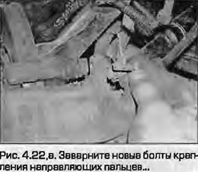
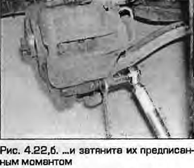
Note: New guide pin mounting bolts are required for installation.
22. Insert the guide mounting bolts, tightening them to the specified torque (fig. 4.22, a, b).
 |
 |
All models
23. Press the brake pedal several times so that the pads are pressed against the brake disc - they are in the working position, and you feel the normal "rigidity" of the pedal (when the amplifier is not working).
24. Perform the above procedure on the other side of the caliper.
25. Install the wheels, lower the vehicle, tighten the wheel mounting bolts to the specified torque - see chapters 1A or 1B.
26. Check the brake fluid level as described in Weekly checks.
Warning: New brake pads need to be "broken in" to achieve full braking efficiency. Therefore, avoid hard braking for the first few hundred kilometers after replacing the pads.