
Attention! Brake pads are always replaced as a set - four pieces on both wheels of the same axle. Never change pads on one wheel, causing uneven braking. Never inhale dust from the pads - it may contain carcinogenic asbestos. Wear a dust mask when working with the brakes. Do not use gasoline for cleaning and washing - only a solvent or methyl alcohol intended for this purpose.
Note: After any loosening of the guide pin mounting bolts, the bolts must be replaced.
1. Place chocks under the front wheels, engage reverse gear (or "P" in the case of an automatic transmission). Raise the rear of the car and install safety supports (see Jacking up a car and installing safety supports). Remove the rear wheels. When removing the wheels, tighten one bolt into each hub to prevent the brake discs from shifting relative to the hub.
2. As described in paragraph 15, release the handbrake lever and release the handbrake cable adjustment to obtain maximum cable slack and ensure that the operating levers of both calipers are fully retracted.
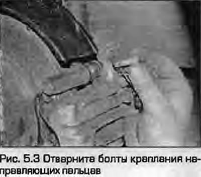
3. Loosen the upper and lower guide pin mounting bolts, holding them with an open-end wrench (Fig. 5.3). New bolts will be required for installation.
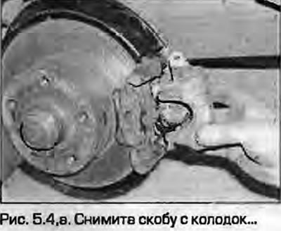
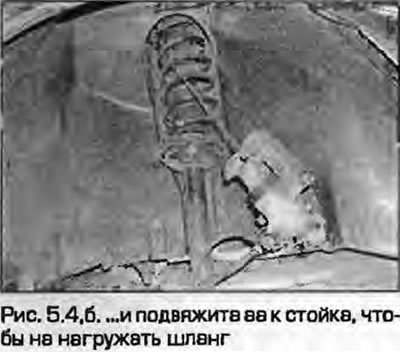
4. Remove the caliper from the mounting bracket. Tie the caliper to the stand with wire so as not to put stress on the brake hose (fig. 5.4, a, b).
 |
 |
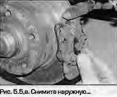
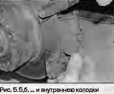
5. Remove the pads (fig. 5.5, a, b).
 |
 |
6. First measure the thickness of the friction material (fig. 4.9). If any pad is damaged or has unacceptable wear (see Specification), replace the entire set of pads to avoid disturbing the brake balance. The pads should also be replaced if at least one of them is oiled - there is no satisfactory way to remove oil from the friction material without changing its structure. If at least one pad has been oiled, find the cause and eliminate it before installing a new set of pads. A set of pads can be purchased from a dealer.
7. If the pads look good, carefully clean them from dirt with a soft wire brush, paying special attention to the back and sides. Clean the grooves in the friction material, remove foreign inclusions. Clean the seats in the caliper and bracket.
8. Before installing the pads, make sure that the guide strut bushings move easily and that their protective covers are intact. Remove dust from the caliper and piston with a brush. Do not inhale it - it may contain carcinogenic asbestos dust. Make sure that the piston dust boots are intact and there are no leaks, corrosion or other damage to the pistons. If these components require attention - see paragraph 9.
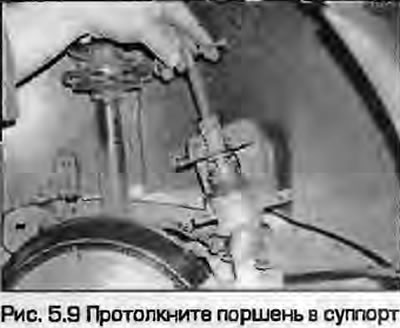
9. If you are installing new pads, the piston must be pressed into the caliper flush with its surface. This can be done by rotating the piston clockwise with a suitable screwdriver by the cutouts in the piston (Fig. 5.9). Monitor the fluid level in the reserve tank - if it exceeds the MAX mark, the fluid must be pumped out using the siphon method - not by mouth (the liquid is poisonous) - with a syringe or a hydrometer, or by connecting a hose to the bleeding nipple (see paragraph 4 p. 12).
10. If provided, remove the protective film from the pads and install the pads with the friction material facing the disc.
11. Place the caliper on the brake pads so that the anti-squeal springs rest correctly against the inner surface of the caliper, are not pinched, and do not protrude into the inspection hole in the bracket.
Note: Installation will require new guide pin mounting bolts.
12. Press the bracket, insert the new guide mounting bolts and tighten them to the specified torque, holding the guide pins with an open-end wrench.
13. Repeat all this with the other support.
14. Press the brake pedal several times to get the pads into their working position. As soon as you feel the pedal's normal "hardness", you can stop pressing.
15. Install the wheels and lower the vehicle. Tighten the wheel bolts to the specified torque - see chapters 1A or 1B.
16. Check the brake fluid level as described in Weekly checks. Adjust the handbrake.
Warning. If new pads have been installed, full braking efficiency will only be achieved after several hundred kilometers of running - the pads must rub in to the disc. Avoid sharp braking during this period.