Repair Chevrolet Repair Toyota Repair Honda Repair AvtoVAZ Repair Mercedes-Benz Repair BMW Repair Opel
Home  |  Contacts  |  Sitemap  |    
English Русский
Български
Беларускі
Український
Српски
Hrvatski
Română
Polski
Slovenský
Magyar
AudiManual.ru


  • AUDI 80
  • AUDI 100
  • AUDI A3
  • AUDI A4
  • AUDI A6
  • AUDI A8
  • AUDI Q
  • OTHER
  • ARTICLES
B8 (2007-2015) B7 (2004-2008) B6 (2000-2006) B6 (2000-2006, petrol) B5 (1994-2001) B5 (1994-2001, petrol)

Vacuum brake booster — checking, removal and installation (Audi A4 B5)

  • Home
  • Audi A4
  • B5 (1994-2001)
  • Chassis
  • Brake system
  • Vacuum brake booster — checking, removal and installation
            0
Table of contents: Examination ↓ Removal ↓ Installation ↓

Examination


1. To check, press the brake pedal several times to release the vacuum, and, holding the pedal down, start the engine. As soon as the engine starts, you should feel a clear movement of the pedal up as the vacuum builds up. Let the engine run for a couple of minutes and turn it off. If now when you press it you feel a "hard" pedal and further pressing makes it even harder, reducing its travel, the booster is working properly.

2. If the booster does not operate as described above, check the booster check valve as described in paragraph 13. On diesel engines, also check the operation of the vacuum pump as described in paragraph 20.

3. If the amplifier still does not work, then the fault is hidden inside it. Since the amplifier is disassemblable only in principle, spare parts are not supplied for it - the faulty amplifier is subject to replacement as a whole.

Removal


4. Remove the brake master cylinder as described in paragraph 10.

5. Carefully remove the vacuum hose tip from the booster, being careful not to damage the seal.

6. Loosen the mounting screws and remove the storage box from under the front panel on the driver's side.

7. Under the dash, locate the servo rod and note how it is connected to the brake pedal. On right-hand drive models, the rod is connected to a lever mounted to the left of the clutch pedal. On left-hand drive models, it is connected directly to the pedal. In both cases, the rod is hinged; to disconnect the rod from the pedal/lever, depress the hinge latches and lift the brake pedal to disconnect the rod hinge end.


8. Remove the Toex bolts securing the servo booster to the pedal bracket and engine shield.

9. Remove the amplifier from the engine compartment. Remove the gasket installed between the amplifier and the shield. Replace the damaged gasket.

Installation


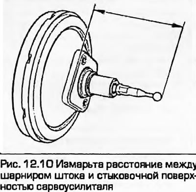
10. Before installation, check the adjustment of the booster rod. After removing the gasket, check the size (fig. 12.10). If adjustment is required, the size can be changed by loosening the lock nut and rotating the rod. After completing the adjustment, tighten the lock nut.

10. Before installation, check the adjustment of the booster rod. After removing the gasket, check…


11. Clean the mating surfaces of the amplifier and the shield, install the gasket, then the amplifier.

12. From the passenger compartment, check that the stem and pedal are properly connected by clicking the hinge into place. Lift the pedal by hand to ensure that the connection is secure.

13. Install the servo booster mounting bolts and tighten them to the specified torque.

14. Adjust the position of the brake light contact sensor as described in paragraph 17.

15. Install a storage box under the front panel.

16. Carefully insert the vacuum hose tip into the booster, being careful not to damage the seal.


17. Install the master cylinder as described in paragraph 10.

18. Bleed the hydraulic system as described in paragraph 2.

19. Bleed the brake hydraulic system as described in chapter 6.
The article was checked by auto expert Timur Bazhenov
This article is available at russian, bulgarian, belarusian, ukrainian, serbian, croatian, romanian, polish, slovak, hungarian

Share information:
Previous articles
Audi A4 B5: Brake system
Next articles

Brake pedal — removal and installation
Master Brake Cylinder — Removal, Repair and Installation
Rear Brake Caliper — Removal, Repair and Installation
Front Brake Caliper — Removal, Repair and Installation
Brake booster check valve
Adjusting the handbrake
Handbrake lever — removal and installation
Handbrake cables — removal and installation


Similar articles on other Audi car models:
Rear brake pads — checking, removal and installation Audi 80 B3 (1986-1991, petrol)
Brake pedal — removal and installation Audi 100 C3 (1982-1990, diesel)
Removal, installation and checking the clutch Audi A3 Type 8L (1996-2003)
Brake booster vacuum — removal and installation Audi A6 C5 Allroad (1999-2005)
Checking brake hoses Audi A8 D2 (1994-2002)
Removal and installation the brake master cylinder, vacuum… Audi Q7 Typ 4L (2005-2015, diesel)
Removal and installation the upper brake light Audi A2 (1999-2005)
Link to this page in different formats


Visitor comments

No comments yet


How much will 48 + 12 =


A4(B8, 2007-2015) 
  • General information
  • Operating instructions
  • Power unit
  • Petrol engines 1.8 l
  • Petrol engines 1.8/2.0 l
  • Petrol engines 3.0 l
  • Petrol engines 3.2 l
  • Fuel system (petrol)
  • Diesel engines 2.0 l (CA*)
  • Diesel engines 2.0 l (CJCB)
  • Diesel engines 2.7/3.0 l
  • Diesel engines 3.0 l
  • Fuel system (diesel)
  • Transmission
  • Manual gearbox 0B1
  • Manual gearbox 0B2
  • Manual gearbox 0B3
  • Manual gearbox 0B4
  • Automatic transmission 0B5
  • Automatic transmission 0B6
  • Automatic transmission 0AW
  • All-wheel drive system
  • Chassis
  • Front suspension
  • Rear suspension
  • Brake system
  • Steering system
  • Body
  • Exterior
  • Interior
  • Seats
  • Doors, locks and windows
  • Security system
  • Heating and air conditioning
  • Electrical equipment
  • Audio system
  • Power devices
  • Equipment and devices
  • Lighting and lamps
  • Electrical circuits
 
A4(B7, 2004-2008) 
  • General information
  • Introduction to manual
  • Troubleshooting
  • Operating instructions
  • Maintenance
  • Power unit
  • Petrol engines 2.0 (ALT)
  • Petrol engines 2.0 (TFSI)
  • Petrol engines 1.8 (MPI)
  • Diesel engines
  • Cooling system
  • Air conditioner
  • Fuel and exhaust system
  • Ignition system
  • Starting and charging
  • Transmission
  • Clutch
  • Manual gearbox
  • Automatic gearbox
  • Drive shafts
  • Chassis
  • Brake system
  • Front suspension
  • Rear suspension
  • Steering
  • Body
  • Exterior
  • Interior
  • Electrical equipment
  • Equipment and devices
  • Lighting and signaling
  • Windscreen wipers and washers
  • Electrical diagrams
  • Electrical diagrams (since 2007)
 
A4(B6, 2000-2006) 
  • General information
  • Vehicle Description
  • User manual
  • Maintenance
  • Power unit
  • Gasoline engine
  • Diesel engine
  • Lubrication system
  • Cooling system
  • Supply system
  • Injection system
  • Exhaust system
  • Ignition and control
  • Transmission
  • Gear box
  • Clutch and drive shafts
  • Chassis
  • Brake system
  • Car suspension
  • Steering
  • Body
  • Heating and ventilation
  • Exterior (external elements)
  • Interior (internal elements)
  • Electrical equipment
  • Power devices
  • Lighting and appliances
  • Electrical circuits
 
A4(B6, 2000-2006, petrol) 
  • General information
  • Introduction to the guide
  • Car care
  • Power unit
  • Engine repair
  • Lubrication system
  • Cooling system
  • Injection and control system
  • Ignition system
  • Power and exhaust system
  • Transmission
  • Clutch and drive shafts
  • Car gearbox
  • Chassis
  • Suspension and wheels
  • Steering
  • Brake system
  • Body
  • Interior
  • Exterior
  • Electrical equipment
  • Equipment and devices
  • Lighting and signaling
  • Power devices
  • Electrical circuits
 
A4(B5, 1994-2001) 
  • General information
  • Introduction to the guide
  • Car care
  • Maintenance (gasoline)
  • Maintenance (diesel)
  • Power unit
  • Gasoline engines
  • Diesel engines
  • Engine overhaul
  • Cooling system
  • Fuel injection (gasoline)
  • Fuel system (diesel)
  • Exhaust system
  • Ignition system
  • Transmission
  • Clutch
  • Mechanical gearbox
  • Automatic gearbox
  • Drive shafts
  • Chassis
  • Brake system
  • Car suspension
  • Steering
  • Body
  • Exterior
  • Interior
  • Doors, locks and windows
  • Heating and ventilation
  • Electrical equipment
  • Power devices
  • Equipment and devices
  • Electrical circuits
 
A4(B5, 1994-2001, petrol) 
  • General information
  • Vehicle description
  • Maintenance
  • Power unit
  • Engine repair
  • Turbocharging
  • Exhaust system
  • Cooling system
  • Ignition system
  • Fuel system
  • Motronic injection system
  • MPI and MPFI injection system
  • Transmission
  • Clutch
  • Gearbox and shafts
  • Chassis
  • Steering
  • Car suspension
  • Brake system
  • Wheels and tires
  • Body
  • Heating and ventilation
  • Body parts
  • Electrical equipment
  • Fuses and relays
  • Power devices
  • Lighting and lamps
  • Tools and devices
  • Electrical circuits
 
AudiManual.ru © 2017-2026 · Mobile version · Feedback · Sitemap: EN BG BY UA RS HR RO PL SK HU · Site search · News and articles
80 B2 · 80 B3 petrol · 80 B3 · 80 B4 · 100 C3 diesel · 100 C3 petrol · 100 C3 · 100 C4 petrol · 100 C4 · A3 Type 8L · A4 B5 petrol · A4 B5 · A4 B6 petrol · A4 B6 · A4 B7 · A4 B8 · A6 C4 · A6 C5 · A6 C5 Allroad · A8 D2 · Q5 Type 8R · Q7 Typ 4L · Audi A2 ·
This site uses cookies 🍪. Click the button to accept this fact.