Repair Chevrolet Repair Toyota Repair Honda Repair AvtoVAZ Repair Mercedes-Benz Repair BMW Repair Opel
Home  |  Contacts  |  Sitemap  |    
English Русский
Български
Беларускі
Український
Српски
Hrvatski
Română
Polski
Slovenský
Magyar
AudiManual.ru


  • AUDI 80
  • AUDI 100
  • AUDI A3
  • AUDI A4
  • AUDI A6
  • AUDI A8
  • AUDI Q
  • OTHER
  • ARTICLES
B8 (2007-2015) B7 (2004-2008) B6 (2000-2006) B6 (2000-2006, petrol) B5 (1994-2001) B5 (1994-2001, petrol)

Rear Brake Caliper — Removal, Repair and Installation (Audi A4 B5)

  • Home
  • Audi A4
  • B5 (1994-2001)
  • Chassis
  • Brake system
  • Rear Brake Caliper — Removal, Repair and Installation
            0
Table of contents: Removal ↓ Repair ↓ Installation ↓
Warning: On models equipped with ABS, disconnect the battery before opening the hydraulic system and do not reconnect it until bleeding and filling the reserve tank with fluid is complete. If this is not done, air may enter the ABS hydraulic system, which will require specialized diagnostic equipment to remove - you will have to contact your dealer for help.


Note: Before starting the procedure, please read the warnings contained in the paragraphs 2 and 5 about the harmfulness of asbestos dust and brake fluid.


Removal


Note: New guide pin mounting bolts are required for installation.


1. Place chocks under the front wheels, engage the rear shift (or "P" in the case of an automatic transmission), raise the rear of the car and install safety supports (see Jacking up a car and installing safety supports). Remove the corresponding wheel. When removing the wheels, tighten one bolt into each hub so that the brake discs do not mix with the hub.

2. As described in paragraph 15, release the handbrake, then release the handbrake cable adjustment so as to obtain maximum slack in the cables.

3. Disconnect the handbrake cable end from the caliper operating lever, pull the cable casing out of the caliper housing.

4. To minimize fluid loss, place a polyethylene circle under the reserve tank cap, creating a hermetic seal (be careful not to damage the sensor). You can use a clamp to clamp the brake hose closer to the caliper.

5. Remove any dirt around the brake pipe connection to the caliper and unscrew the union nut. Carefully remove the pipe and tape the end to prevent dirt from getting into the system. Clean up any spilled fluid immediately.


6. Unscrew the caliper guide pin mounting bolts, holding the pins with a thin open-end wrench. Throw away the bolts - new ones are required for installation.

7. Remove the caliper from the mounting bracket and unscrew it from the brake hose tip. Plug the hose and the hole in the caliper to prevent dirt from getting in and fluid from spilling in vain. Immediately rinse off any soaked fluid with cold water. Remove the brake pads. Unscrew the bolts and remove the caliper mounting bracket.

Repair


Note: The handbrake mechanism of the caliper cannot be repaired. If the mechanism is faulty or fluid leaks through the seal of its lever, the entire caliper must be replaced.


8. After installing the support on the workbench, clean it, but do not inhale the dust, as it is harmful to health.

9. Remove the piston by turning it counterclockwise from the caliper with a screwdriver or a square bar, inserting it into the cutouts on the piston. If the piston rotates freely, but does not come out of the caliper anymore, it can be pulled out further by hand, since it is held in place only by the seal.

10. Using a blunt tool such as a plastic knife, remove the piston seal from the groove in the cylinder, being careful not to damage the cylinder itself.

11. Remove the guide bushings with covers from the caliper struts.

12. Inspect the caliper components as described in paragraph 10replace defective components with new ones (handbrake mechanism - disassemblable).

13. Make sure all components are clean and dry.


Fig. 9.13. Components of the rear brake caliper: 1. Self-locking bolt; 2. Support; 3. Bleeding…

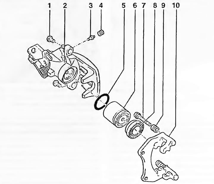
Fig. 9.13. Components of the rear brake caliper: 1. Self-locking bolt; 2. Support; 3. Bleeding nipple; 4. Cap; 5. Piston seal; 6. Piston; 7. Guide pin; 8. Dust cover; 9. Dust cover; 10. Caliper mounting bracket


14. Dip the piston and new piston seal into clean brake fluid. Lubricate the cylinder surface with it. Install the new piston seal into the cylinder groove and install the piston.

15. Install the new dust boot into the caliper groove. Carefully and evenly insert the piston into the cylinder with rotating movements. Screw the piston into the cylinder clockwise until it stops and install the dust boot into the piston groove.

16. Apply the grease supplied with the repair kit or a good quality high temperature brake grease or non-stick compound to the guide bushings. Install the bushings onto the caliper and install the new boots, fitting them into the groove on the caliper and bushings.

17. Before installation, fill the caliper with fresh brake fluid by loosening the bleed nipple and bleeding the cylinder until bubbles stop coming out of the nipple.

Installation


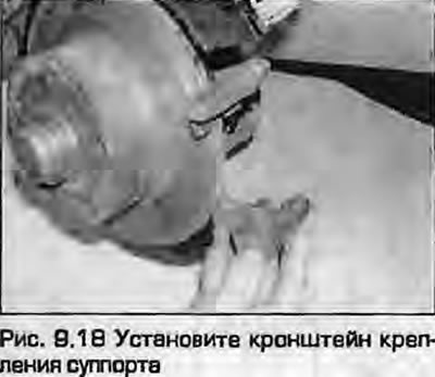
18. Install the caliper bracket and secure with new bolts, tightening them to the specified torque (Fig. 9.18). Install the brake pads as described in paragraph 5.


18. Install the caliper bracket and secure with new bolts, tightening them to the specified torque…


19. Wipe the brake pipe joint clean. Install the caliper onto the brake hose joint, screw it on and install the caliper onto the disc. Install the new guide pin mounting bolts, tightening them to the specified torque.

20. Remove the clamp from the brake hose or remove the plastic from under the reservoir cap.

21. Bleed the hydraulic system as described in paragraph 2. It may be enough to pump only one disturbed circuit.

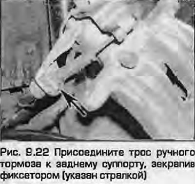
22. Attach the cable end to the operating lever, securing it with the clamp and adjust the cable as described in paragraph 16.

22. Attach the cable end to the operating lever, securing it with the clamp and adjust the cable as…


23. Install the wheel, lower the vehicle and tighten the wheel bolts to the specified torque as described in Chapter 1A or 1B.

(The text is based on materials from the website: AudiManual.ru)
The article was checked by auto expert Timur Bazhenov
This article is available at russian, bulgarian, belarusian, ukrainian, serbian, croatian, romanian, polish, slovak, hungarian

Share information:
Previous articles
Audi A4 B5: Brake system
Next articles

Front Brake Caliper — Removal, Repair and Installation
Rear brake disc — inspection, removal and installation
Front brake disc — inspection, removal and installation
Rear brake pads — replacement
Master Brake Cylinder — Removal, Repair and Installation
Brake pedal — removal and installation
Vacuum brake booster — checking, removal and installation
Brake booster check valve


Similar articles on other Audi car models:
Rear Brake Caliper — Removal and Installation Audi 80 B3 (1986-1991, petrol)
Rear brake disc — removal and installation Audi 100 C3 (1982-1990, diesel)
Removal and installation the brake disc / caliper Audi A3 Type 8L (1996-2003)
Rear brake pads with caliper C43 — removal and installation Audi A6 C5 Allroad (1999-2005)
Rear Caliper Repair Audi A8 D2 (1994-2002)
Removal the brake caliper and rear brake bracket Audi Q5 Type 8R (2008-2017)
Removal and installation the thermostat housing and coolant pipe… Audi A2 (1999-2005)
Link to this page in different formats


Visitor comments

No comments yet


How much will 44 + 43 =


A4(B8, 2007-2015) 
  • General information
  • Operating instructions
  • Power unit
  • Petrol engines 1.8 l
  • Petrol engines 1.8/2.0 l
  • Petrol engines 3.0 l
  • Petrol engines 3.2 l
  • Fuel system (petrol)
  • Diesel engines 2.0 l (CA*)
  • Diesel engines 2.0 l (CJCB)
  • Diesel engines 2.7/3.0 l
  • Diesel engines 3.0 l
  • Fuel system (diesel)
  • Transmission
  • Manual gearbox 0B1
  • Manual gearbox 0B2
  • Manual gearbox 0B3
  • Manual gearbox 0B4
  • Automatic transmission 0B5
  • Automatic transmission 0B6
  • Automatic transmission 0AW
  • All-wheel drive system
  • Chassis
  • Front suspension
  • Rear suspension
  • Brake system
  • Steering system
  • Body
  • Exterior
  • Interior
  • Seats
  • Doors, locks and windows
  • Security system
  • Heating and air conditioning
  • Electrical equipment
  • Audio system
  • Power devices
  • Equipment and devices
  • Lighting and lamps
  • Electrical circuits
 
A4(B7, 2004-2008) 
  • General information
  • Introduction to manual
  • Troubleshooting
  • Operating instructions
  • Maintenance
  • Power unit
  • Petrol engines 2.0 (ALT)
  • Petrol engines 2.0 (TFSI)
  • Petrol engines 1.8 (MPI)
  • Diesel engines
  • Cooling system
  • Air conditioner
  • Fuel and exhaust system
  • Ignition system
  • Starting and charging
  • Transmission
  • Clutch
  • Manual gearbox
  • Automatic gearbox
  • Drive shafts
  • Chassis
  • Brake system
  • Front suspension
  • Rear suspension
  • Steering
  • Body
  • Exterior
  • Interior
  • Electrical equipment
  • Equipment and devices
  • Lighting and signaling
  • Windscreen wipers and washers
  • Electrical diagrams
  • Electrical diagrams (since 2007)
 
A4(B6, 2000-2006) 
  • General information
  • Vehicle Description
  • User manual
  • Maintenance
  • Power unit
  • Gasoline engine
  • Diesel engine
  • Lubrication system
  • Cooling system
  • Supply system
  • Injection system
  • Exhaust system
  • Ignition and control
  • Transmission
  • Gear box
  • Clutch and drive shafts
  • Chassis
  • Brake system
  • Car suspension
  • Steering
  • Body
  • Heating and ventilation
  • Exterior (external elements)
  • Interior (internal elements)
  • Electrical equipment
  • Power devices
  • Lighting and appliances
  • Electrical circuits
 
A4(B6, 2000-2006, petrol) 
  • General information
  • Introduction to the guide
  • Car care
  • Power unit
  • Engine repair
  • Lubrication system
  • Cooling system
  • Injection and control system
  • Ignition system
  • Power and exhaust system
  • Transmission
  • Clutch and drive shafts
  • Car gearbox
  • Chassis
  • Suspension and wheels
  • Steering
  • Brake system
  • Body
  • Interior
  • Exterior
  • Electrical equipment
  • Equipment and devices
  • Lighting and signaling
  • Power devices
  • Electrical circuits
 
A4(B5, 1994-2001) 
  • General information
  • Introduction to the guide
  • Car care
  • Maintenance (gasoline)
  • Maintenance (diesel)
  • Power unit
  • Gasoline engines
  • Diesel engines
  • Engine overhaul
  • Cooling system
  • Fuel injection (gasoline)
  • Fuel system (diesel)
  • Exhaust system
  • Ignition system
  • Transmission
  • Clutch
  • Mechanical gearbox
  • Automatic gearbox
  • Drive shafts
  • Chassis
  • Brake system
  • Car suspension
  • Steering
  • Body
  • Exterior
  • Interior
  • Doors, locks and windows
  • Heating and ventilation
  • Electrical equipment
  • Power devices
  • Equipment and devices
  • Electrical circuits
 
A4(B5, 1994-2001, petrol) 
  • General information
  • Vehicle description
  • Maintenance
  • Power unit
  • Engine repair
  • Turbocharging
  • Exhaust system
  • Cooling system
  • Ignition system
  • Fuel system
  • Motronic injection system
  • MPI and MPFI injection system
  • Transmission
  • Clutch
  • Gearbox and shafts
  • Chassis
  • Steering
  • Car suspension
  • Brake system
  • Wheels and tires
  • Body
  • Heating and ventilation
  • Body parts
  • Electrical equipment
  • Fuses and relays
  • Power devices
  • Lighting and lamps
  • Tools and devices
  • Electrical circuits
 
AudiManual.ru © 2017-2026 · Mobile version · Feedback · Sitemap: EN BG BY UA RS HR RO PL SK HU · Site search · News and articles
80 B2 · 80 B3 petrol · 80 B3 · 80 B4 · 100 C3 diesel · 100 C3 petrol · 100 C3 · 100 C4 petrol · 100 C4 · A3 Type 8L · A4 B5 petrol · A4 B5 · A4 B6 petrol · A4 B6 · A4 B7 · A4 B8 · A6 C4 · A6 C5 · A6 C5 Allroad · A8 D2 · Q5 Type 8R · Q7 Typ 4L · Audi A2 ·
This site uses cookies 🍪. Click the button to accept this fact.