
Warning: On models equipped with ABS, before disconnecting the hydraulic connections (opening the system) disconnect the battery and do not connect it until the bleeding is complete. If this is not done, air can get into the return pump of the system, from where it is very difficult to expel, and in some cases impossible.
Note: Before you begin, please read the warning at the beginning paragraph 8 about the dangers of brake fluid.
Removal
1. Apply the handbrake, raise the front of the car and install safety stands. Remove the left wheel.
2. Attach a piece of hose to the bleed nipple of the left front wheel, lowering the other end into the jar, as described in paragraph 2. Open the bleed screw and press the brake pedal several times to expel as much fluid as possible from the master cylinder. When the fluid flow dries up, tighten the nipple.
3. Place a rag under the master cylinder to absorb the fluid. Disconnect the feed hose from the cylinder and plug the holes to prevent further fluid leakage and dirt from getting into the system.
4. Disconnect the wiring from the fluid level sensor in the reserve tank.
5. Wipe the area around the pipe connections on the side of the master cylinder and lay out a rag. Note the location and connection of the pipes, unscrew the connection nuts and remove the pipes. Plug the pipes and holes to prevent dirt from getting in. Wash off any spilled liquid immediately with cold water.
6. Pull the seal off the engine shield in front of the angry cylinder. Release the wiring harness from the fasteners and lift it up so that the cylinder can be removed.
7. Unscrew the two nuts securing the cylinder to the servo booster and remove it from the engine compartment. Remove the sealing ring installed at the rear of the cylinder and discard it - a new one is required for installation (Fig. 10.7).
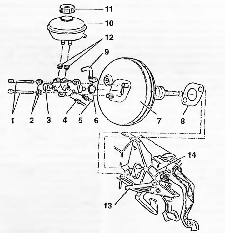
Fig. 10.7. Assemble the parts of the master cylinder and servo amplifier: 1. Bolt T45; 2. Self-locking nut; 3. Master cylinder; 4. Brake pipe; 5. Brake pipe; 6. Compaction; 7. Amplifier; 8. Gasket; 9. Vacuum hose; 10. Reserve tank; 11. Lid; 12. Seals; 13. Feed hose; 14. Motor shield
Note: If you are removing only the master cylinder, do not disturb the Torx head bolts - they also secure the servo booster.
Repair
8. The faulty cylinder must be replaced. Audi/VAG repair kits are not included in spare parts - the cylinder must be replaced as a whole.
9. The only spare parts are the rubber seals of the reserve reservoir. If the seals are damaged, remove the reservoir from them and remove the seals. Lubricate the new seals with clean brake fluid and insert them into the cylinder so that the seals protrude from the housing by approximately 1 mm.
Installation
10. Make sure the mating surfaces are clean and install a new O-ring on the rear end of the master cylinder.
11. Install the cylinder on the booster studs so that the booster pushrod enters the cylinder piston in the middle. Ask an assistant to press the brake pedal lightly to move the pushrod toward the cylinder.
12. Tighten the mounting nuts to the specified torque.
13. Wipe the connections and connect the brake pipes, tighten the connection nuts to the specified torque.
14. Connect the clutch master cylinder hose to the reservoir tank and tighten the clamp securely.
15. Connect the wiring connector to the fluid level sensor.
16. Secure the wiring and restore the engine shield seal.
17. Fill the reserve reservoir with fresh brake fluid and bleed the hydraulic systems as described in paragraph 2 and chapter 6.
[The original article is located on the online resource «AudiManual»]