Repair Chevrolet Repair Toyota Repair Honda Repair AvtoVAZ Repair Mercedes-Benz Repair BMW Repair Opel
Home  |  Contacts  |  Sitemap  |    
English Русский
Български
Беларускі
Український
Српски
Hrvatski
Română
Polski
Slovenský
Magyar
AudiManual.ru


  • AUDI 80
  • AUDI 100
  • AUDI A3
  • AUDI A4
  • AUDI A6
  • AUDI A8
  • AUDI Q
  • OTHER
  • ARTICLES
B8 (2007-2015) B7 (2004-2008) B6 (2000-2006) B6 (2000-2006, petrol) B5 (1994-2001) B5 (1994-2001, petrol)

Front Brake Caliper — Removal, Repair and Installation (Audi A4 B5)

  • Home
  • Audi A4
  • B5 (1994-2001)
  • Chassis
  • Brake system
  • Front Brake Caliper — Removal, Repair and Installation
            0
Table of contents: Removal ↓ Repair ↓ Installation ↓
Warning: On models equipped with ABS, disconnect the battery before opening the hydraulic system and do not reconnect it until the bleeding operation is complete and the reserve tank is filled with fluid. If this is not done, air may enter the ABS hydraulic system. To remove this, specialized diagnostic equipment will be required - you will have to contact the dealer for help.


Note: Before you begin, please refer to the warnings at the beginning of the paragraphs 2 and 4, containing information about the harmfulness of brake fluid and asbestos dust.


Removal


1. Apply the handbrake and lift the front of the car with a jack, install safety supports. Remove the corresponding wheel. When removing the wheels, tighten one bolt into the hubs so that the brake discs do not shift relative to the hub.

2. Remove the cap from the brake fluid reserve reservoir and place a circle of polyethylene film underneath it to seal the cap tightly and minimize brake fluid loss when unscrewing the hose. Alternatively, you can clamp the hose with a clamp or a parrot wrench.

3. If necessary, disconnect the wiring from the brake pad wear sensor, disconnect the sensor from the connector on the caliper bracket.

4. Clean the area around the tube connection. Loosen the hose connection nut. Remove the mounting bracket from the caliper and move the tube away. Plug the tube and the hole in the caliper to prevent dirt from getting into the system and brake fluid from spilling. Immediately wash off any spilled fluid with cold water.


5. On models with ATE/Teves calipers, carefully pry up the retaining spring with a screwdriver. Remove the plugs from the guide bushings and unscrew the guide mounting bolts.

6. On models with Lucas calipers, hold the guide pins with an open-end wrench and loosen and remove the bolts that secure them

7. Remove the caliper, freeing it from the wear sensor wiring (if any). Remove the inner brake shoe from the piston and the outer shoe from the caliper bracket. Remove the bolts and the caliper bracket.

Repair


8. On the workbench, clean and wash the caliper from dirt and rust using brake cleaning fluid, being careful not to inhale the dust to avoid harm to your health.

9. Remove the piston from the caliper body and remove the dust cover.

10. Using a blunt tool such as an old plastic knife, remove the hydraulic seal from the cylinder, being very careful not to damage the cylinder surface.

11. Wash all components thoroughly using only a special liquid - methyl or isopropyl alcohol. Do not use mineral solvents such as kerosene or gasoline for washing, they are aggressive for rubber hydraulic parts. Dry the components immediately with compressed air or a lint-free cloth. Blow out the channels with compressed air.

12. Replace damaged and worn parts. Pay special attention to the surface of the cylinder and piston. If there are scratches, abrasions or corrosion on them, the parts must be replaced. Check the condition of the guide pins and the corresponding bores in the caliper. The pins should not be damaged and should move easily enough in the bores, but not dangle in them. If in doubt, replace the defective parts.


13. If you plan to install the old caliper back, then purchase the necessary parts for it; the dealer has them in various combinations. All rubber seals and dust boots of the caliper must be replaced - an axiom. Never use old seals and dust boots.

14. Before assembly, make sure that all components are absolutely clean and dry (fig. 8.14, a, 6).

Fig. 8.14, a. Components of the Tevee/ATE front caliper: 1. Plug; 2. Guide pins (bolts); 3.…

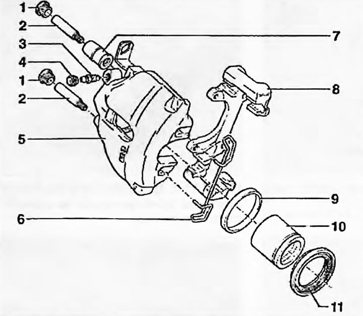
Fig. 8.14, a. Components of the Tevee/ATE front caliper: 1. Plug; 2. Guide pins (bolts); 3. Bleeding nipple; 4. Cap; 5. Caliper (bracket); 6. Brake shoe retaining spring; 7. Guide bushings; 8. Caliper mounting bracket; 9. Piston seal; 10. Piston; 11. Dust cover


Fig. 8.14, b. Components of the Lucas front caliper: 1. Cap; 2. Bleeding nipple; 3. Caliper…

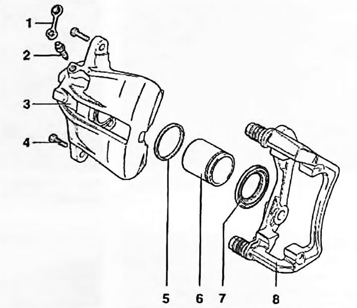
Fig. 8.14, b. Components of the Lucas front caliper: 1. Cap; 2. Bleeding nipple; 3. Caliper (bracket); 4. Guide rail mounting bolts; 5. Piston seal; 6. Piston; 7. Dust cover; 8. Caliper mounting bracket


15. Immerse the piston and new seal in clean brake fluid and lubricate the inner surface of the cylinder with it.

16. Install the piston seal into the cylinder groove using only finger force - using tools may damage the seal.

17. Install the new dust boot on the piston. Insert the piston into the cylinder. Gently press the piston into the cylinder, turning it slightly so that it enters without tilting. Press the piston completely into the cylinder until the outer edge of the dust boot fits into the groove on the caliper.

18. If replacing guide bushings, push the old bushings out of the housing and press in the new ones.

19. Before installation, fill the caliper with fresh brake fluid by unscrewing the bleed nipple and bleeding it until bubbles stop coming out of the nipple.

Installation


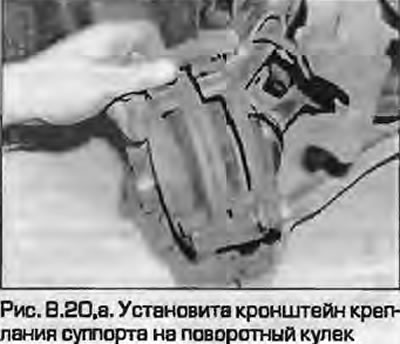
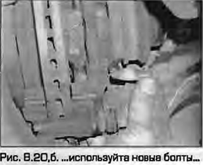
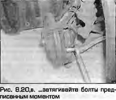
20. Bolt the caliper bracket to the steering knuckle using new bolts and tightening them to the specified torque (fig. 8.20, a-c). Install the brake pads as described in paragraph 4. Place the bracket over the pads.

20. Bolt the caliper bracket to the steering knuckle using new bolts and tightening them to the…

20. Bolt the caliper bracket to the steering knuckle using new bolts and tightening them to the…


21. Tighten the guide pin mounting bolts to the specified torque. Install the plugs on the bushings.


Note: On Lucas models, install new pin retaining bolts.


22. Attach the brake pipe and mounting bracket to the caliper. Tighten the bracket mounting bolt and pipe union nut to the specified torques.

23. Install the shoe retaining spring.

24. Properly route the wiring into the lower plug loop and connect the brake pad wear sensor wiring connector to the caliper bracket.

25. Remove the clamp or plastic circle (what was installed) and bleed the hydraulic system as described in paragraph 2. Please note that it may be sufficient to pump only one disturbed circuit.

26. Install the wheel, lower the vehicle to the ground and tighten the wheel bolts to the specified torque as described in Chapter 1A or 1B.
The article was checked by auto expert Timur Bazhenov
This article is available at russian, bulgarian, belarusian, ukrainian, serbian, croatian, romanian, polish, slovak, hungarian

Share information:
Previous articles
Audi A4 B5: Brake system
Next articles

Rear brake disc — inspection, removal and installation
Front brake disc — inspection, removal and installation
Rear brake pads — replacement
Front brake pads — replacement
Rear Brake Caliper — Removal, Repair and Installation
Master Brake Cylinder — Removal, Repair and Installation
Brake pedal — removal and installation
Vacuum brake booster — checking, removal and installation


Similar articles on other Audi car models:
Front Brake Caliper — Removal and Installation Audi 80 B3 (1986-1991, petrol)
Removal and installation the front brake caliper Audi 100 C4 (1990-1994)
Removal and installation the brake disc / caliper Audi A3 Type 8L (1996-2003)
Front Brake Pads with Caliper FNR-G60 — Removal and Installation Audi A6 C5 Allroad (1999-2005)
Repair of the front caliper FN-3 Audi A8 D2 (1994-2002)
Removal the brake caliper and front brake bracket Audi Q5 Type 8R (2008-2017)
Brake mechanism with floating caliper, front brake disc Audi A2 (1999-2005)
Link to this page in different formats


Visitor comments

No comments yet


How much will 25 + 17 =


A4(B8, 2007-2015) 
  • General information
  • Operating instructions
  • Power unit
  • Petrol engines 1.8 l
  • Petrol engines 1.8/2.0 l
  • Petrol engines 3.0 l
  • Petrol engines 3.2 l
  • Fuel system (petrol)
  • Diesel engines 2.0 l (CA*)
  • Diesel engines 2.0 l (CJCB)
  • Diesel engines 2.7/3.0 l
  • Diesel engines 3.0 l
  • Fuel system (diesel)
  • Transmission
  • Manual gearbox 0B1
  • Manual gearbox 0B2
  • Manual gearbox 0B3
  • Manual gearbox 0B4
  • Automatic transmission 0B5
  • Automatic transmission 0B6
  • Automatic transmission 0AW
  • All-wheel drive system
  • Chassis
  • Front suspension
  • Rear suspension
  • Brake system
  • Steering system
  • Body
  • Exterior
  • Interior
  • Seats
  • Doors, locks and windows
  • Security system
  • Heating and air conditioning
  • Electrical equipment
  • Audio system
  • Power devices
  • Equipment and devices
  • Lighting and lamps
  • Electrical circuits
 
A4(B7, 2004-2008) 
  • General information
  • Introduction to manual
  • Troubleshooting
  • Operating instructions
  • Maintenance
  • Power unit
  • Petrol engines 2.0 (ALT)
  • Petrol engines 2.0 (TFSI)
  • Petrol engines 1.8 (MPI)
  • Diesel engines
  • Cooling system
  • Air conditioner
  • Fuel and exhaust system
  • Ignition system
  • Starting and charging
  • Transmission
  • Clutch
  • Manual gearbox
  • Automatic gearbox
  • Drive shafts
  • Chassis
  • Brake system
  • Front suspension
  • Rear suspension
  • Steering
  • Body
  • Exterior
  • Interior
  • Electrical equipment
  • Equipment and devices
  • Lighting and signaling
  • Windscreen wipers and washers
  • Electrical diagrams
  • Electrical diagrams (since 2007)
 
A4(B6, 2000-2006) 
  • General information
  • Vehicle Description
  • User manual
  • Maintenance
  • Power unit
  • Gasoline engine
  • Diesel engine
  • Lubrication system
  • Cooling system
  • Supply system
  • Injection system
  • Exhaust system
  • Ignition and control
  • Transmission
  • Gear box
  • Clutch and drive shafts
  • Chassis
  • Brake system
  • Car suspension
  • Steering
  • Body
  • Heating and ventilation
  • Exterior (external elements)
  • Interior (internal elements)
  • Electrical equipment
  • Power devices
  • Lighting and appliances
  • Electrical circuits
 
A4(B6, 2000-2006, petrol) 
  • General information
  • Introduction to the guide
  • Car care
  • Power unit
  • Engine repair
  • Lubrication system
  • Cooling system
  • Injection and control system
  • Ignition system
  • Power and exhaust system
  • Transmission
  • Clutch and drive shafts
  • Car gearbox
  • Chassis
  • Suspension and wheels
  • Steering
  • Brake system
  • Body
  • Interior
  • Exterior
  • Electrical equipment
  • Equipment and devices
  • Lighting and signaling
  • Power devices
  • Electrical circuits
 
A4(B5, 1994-2001) 
  • General information
  • Introduction to the guide
  • Car care
  • Maintenance (gasoline)
  • Maintenance (diesel)
  • Power unit
  • Gasoline engines
  • Diesel engines
  • Engine overhaul
  • Cooling system
  • Fuel injection (gasoline)
  • Fuel system (diesel)
  • Exhaust system
  • Ignition system
  • Transmission
  • Clutch
  • Mechanical gearbox
  • Automatic gearbox
  • Drive shafts
  • Chassis
  • Brake system
  • Car suspension
  • Steering
  • Body
  • Exterior
  • Interior
  • Doors, locks and windows
  • Heating and ventilation
  • Electrical equipment
  • Power devices
  • Equipment and devices
  • Electrical circuits
 
A4(B5, 1994-2001, petrol) 
  • General information
  • Vehicle description
  • Maintenance
  • Power unit
  • Engine repair
  • Turbocharging
  • Exhaust system
  • Cooling system
  • Ignition system
  • Fuel system
  • Motronic injection system
  • MPI and MPFI injection system
  • Transmission
  • Clutch
  • Gearbox and shafts
  • Chassis
  • Steering
  • Car suspension
  • Brake system
  • Wheels and tires
  • Body
  • Heating and ventilation
  • Body parts
  • Electrical equipment
  • Fuses and relays
  • Power devices
  • Lighting and lamps
  • Tools and devices
  • Electrical circuits
 
AudiManual.ru © 2017-2026 · Mobile version · Feedback · Sitemap: EN BG BY UA RS HR RO PL SK HU · Site search · News and articles
80 B2 · 80 B3 petrol · 80 B3 · 80 B4 · 100 C3 diesel · 100 C3 petrol · 100 C3 · 100 C4 petrol · 100 C4 · A3 Type 8L · A4 B5 petrol · A4 B5 · A4 B6 petrol · A4 B6 · A4 B7 · A4 B8 · A6 C4 · A6 C5 · A6 C5 Allroad · A8 D2 · Q5 Type 8R · Q7 Typ 4L · Audi A2 ·
This site uses cookies 🍪. Click the button to accept this fact.