
Repair Chevrolet Repair Toyota Repair Honda Repair AvtoVAZ Repair Mercedes-Benz Repair BMW Repair Opel
Home  |  Contacts  |  Sitemap  |    
English Русский
Български
Беларускі
Український
Српски
Hrvatski
Română
Polski
Slovenský
Magyar
AudiManual.ru


  • AUDI 80
  • AUDI 100
  • AUDI A3
  • AUDI A4
  • AUDI A6
  • AUDI A8
  • AUDI Q
  • OTHER
  • ARTICLES
C4 (1990-1994) C4 (1990-1994, petrol) C3 (1982-1990) C3 (1982-1990, petrol) C3 (1982-1990, diesel)

Removal and installation the ignition distributor sensor (Audi 100 C3)

  • Home
  • Audi 100
  • C3 (1982-1990, petrol)
  • 4 cylinder engine
  • Ignition system
  • Removal and installation the ignition distributor sensor
            0
Table of contents: Removal ↓ Installation ↓

Removal


Disconnect the spark plug wires and the ignition coil high-voltage wire from the ignition distributor.

Release the spring clips and remove the distributor cap.

Disconnect the ignition distributor sensor connector.

Remove the ignition distributor rotor.

Remove the distributor sensor housing flange.

Remove the ignition distributor sensor.

Installation


Turn the engine crankshaft to the position corresponding to the TDC of the piston of the 1st cylinder, aligning the mark on the toothed pulley of the camshaft with the plane of the cylinder head cover gasket.
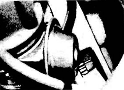
Marks for setting the ignition timing on the crankshaft flywheel and on the clutch housing

Marks for setting the ignition timing on the crankshaft flywheel and on the clutch housing


Make sure that the slot of the distributor shaft drive is parallel to the crankshaft axis and, if necessary, set it in the correct position.

Before installing the ignition distributor sensor, turn the shaft so that the rotor spacer plate is directed towards the mark on the housing, which corresponds to the TDC of the compression stroke of the piston of the 1st cylinder.

Install the ignition distributor sensor into place, ensuring that the distributor sensor drive shaft coupling is oriented correctly.


Replace the flange and tighten the lock nut.

Replace the distributor cap, making sure it is not cracked or dirty.

Connect the high-voltage wires and connect the ignition distributor sensor connector.
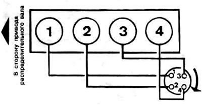
High voltage wire connection diagram

High voltage wire connection diagram


Set the ignition timing.
The article was checked by auto expert Maxim Rybakov
This article is available at russian, bulgarian, belarusian, ukrainian, serbian, croatian, romanian, polish, slovak, hungarian

Share information:
Previous articles
Audi 100 C3: Ignition system
Next articles

The structure and principle of operation of the electronic…
Ignition system — technical characteristics
Ignition distributor sensor parts
Setting the ignition timing
Ignition system troubleshooting diagram, voltage testing


Similar articles on other Audi car models:
Electrical diagram of the Hall sensor, ignition coil with… Audi 80 B4 (1991-1996)
Ignition switch and engine start Audi A3 Type 8L (1996-2003)
Ignition distributor Audi A4 B5 (1994-2001, petrol)
Ignition distributor runner Audi A6 C4 (1994-1997)
Ignition switch Audi A8 D2 (1994-2002)
Ignition System — Control Data Audi Q5 Type 8R (2008-2017)
Engine speed sensor Audi A2 (1999-2005)
Link to this page in different formats


Visitor comments

No comments yet


How much will 24 + 40 =


100(C4, 1990-1994) 
  • General information
  • User manual
  • Power unit
  • Engine repair
  • Ignition system
  • Fuel system (gasoline)
  • Fuel system (diesel)
  • Lubrication system
  • Cooling system
  • Exhaust system
  • Transmission
  • Clutch
  • Car gearbox
  • Drive shafts
  • Chassis
  • Car suspension
  • Steering
  • Wheels and tires
  • Brake system
  • Body
  • Ventilation and heating
  • Body repair
  • Electrical equipment
  • Power devices
  • Lighting and appliances
  • Electrical circuits
 
100(C4, 1990-1994, petrol) 
  • General information
  • Operation and maintenance
  • Power unit
  • Engine repair
  • Exhaust system
  • Cooling system
  • Supply system
  • Air filter
  • Mono-Motronic injection system
  • Digifant injection system
  • KE-III-Jetronic and KE-Motronic
  • MPI and MPFI injection system
  • Transmission
  • Clutch
  • Car gearbox
  • Chassis
  • Suspension and steering
  • Brake system
  • Wheels and tires
  • Body
  • Exterior
  • Interior
  • Electrical equipment
  • Fuses and relays
  • Power devices
  • Ignition system
  • Lighting and signaling
  • Equipment and devices
  • Electrical circuits
 
100(C3, 1982-1990) 
  • General information
  • User manual
  • Maintenance
  • Specifications
  • Power unit
  • Engines 4-cylinder
  • Engines 5-cylinder
  • Diesel engine
  • Cooling system
  • Power system (carburetor)
  • Power system (injector)
  • Fuel system (diesel)
  • Transistor ignition system
  • Electronic ignition system
  • Transmission
  • Clutch
  • 4 speed gearbox 014
  • 5 speed gearbox 013 and 093
  • 5 speed gearbox 016 and 012
  • Shift mechanism KP 016
  • Automatic transmission
  • Front wheel drive
  • Chassis
  • Front suspension
  • Rear suspension
  • Steering
  • Brake system
  • Body
  • Body elements
  • Electrical equipment
  • Lighting and appliances
  • Power devices
  • Electrical circuits
 
100(C3, 1982-1990, petrol) 
  • General information
  • Maintenance and operation
  • 4 cylinder engine
  • Engine repair
  • Cooling and lubrication system
  • Supply system
  • Ignition system
  • 5 cylinder engine
  • Engine repair
  • Cooling and lubrication system
  • Supply system
  • Ignition system
  • Transmission
  • Clutch and drive shafts
  • 4 speed gearbox 014
  • 5 speed gearbox 013 and 093
  • 5 speed gearbox 016 and 012
  • Automatic gearbox
  • Chassis
  • Steering
  • Front suspension
  • Rear suspension
  • Brake system
  • Body
  • Body elements
  • Doors, locks and windows
  • Body repair
  • Electrical equipment
  • Equipment and devices
  • Power devices
  • Electrical circuits
 
100(C3, 1982-1990, diesel) 
  • General information
  • User manual
  • Maintenance
  • Troubleshooting
  • Power unit
  • Engine in a car
  • Engine removed
  • Cooling system
  • Fuel system
  • Exhaust system
  • Starting and charging
  • Preheating
  • Transmission
  • Clutch
  • Mechanical gearbox
  • Automatic gearbox
  • Drive shafts
  • Chassis
  • Brake system
  • Suspension
  • Steering
  • Body
  • Exterior
  • Interior
  • Electrical equipment
  • Equipment and devices
  • Electrical circuits
 
AudiManual.ru © 2017-2026 · Mobile version · Feedback · Sitemap: EN BG BY UA RS HR RO PL SK HU · Site search · News and articles
80 B2 · 80 B3 petrol · 80 B3 · 80 B4 · 100 C3 diesel · 100 C3 petrol · 100 C3 · 100 C4 petrol · 100 C4 · A3 Type 8L · A4 B5 petrol · A4 B5 · A4 B6 petrol · A4 B6 · A4 B7 · A4 B8 · A6 C4 · A6 C5 · A6 C5 Allroad · A8 D2 · Q5 Type 8R · Q7 Typ 4L · Audi A2 ·
This site uses cookies 🍪. Click the button to accept this fact.