
Table of contents: Selector lever cable ↓ Removal and installation the gear… ↓
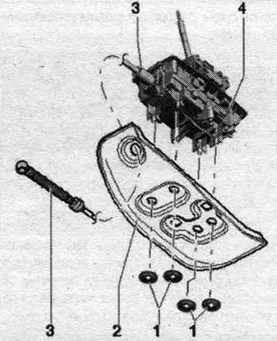
Selector lever cable
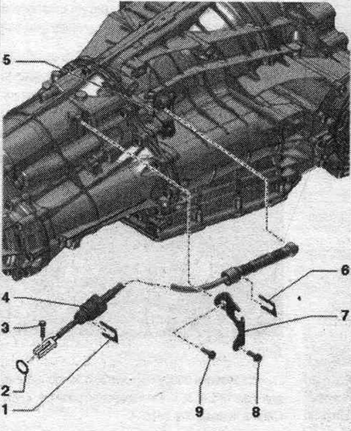
1. Selector cable retaining clip on the shift drive functional block.
2. Sealing ring: replace.
3. Bolt: for adjusting the selector cable; fastening on the functional block of the gear shift mechanism; 13 Nm.
4. Gear selector cable: do not bend or kink; if the rubber bushing is damaged, replace the selector cable; before installation, lightly lubricate the ball joint with polyurea grease -G 052 142 A2-; install the rubber cuff on the gearbox side without distortions; after adjusting the gear selection cable, it is necessary to perform the corresponding "Guided Function" using a diagnostic tester.
5. Gear shift lever.
6. Locking clamp of the selector cable to the cable support.
7. Cable stop.
8/9. Bolt: 8 Nm.
Removal and installation the gear selector cable
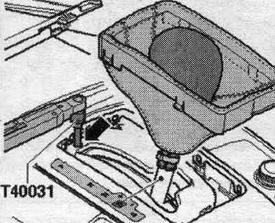
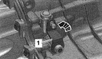
Pull the parking brake button to engage the electric parking brake. mechanical parking brake. Shift the automatic gearbox selector to position "D". Carefully push the selector lever gaiter sideways with the wedge "3409" "arrows" and fold it upwards. Through the hole "arrow" in the gearshift mechanism, loosen the automatic gearbox selector cable bolt 1 turn using the T40031 socket. Only loosen the clamping bolt — do not unscrew it. Access to the clamp bolt is only possible in the "D" position. With the clamp bolt loosened, the automatic transmission selector must remain in the "D" position.
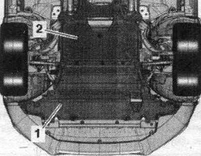
Remove sound insulation "1" and "2".
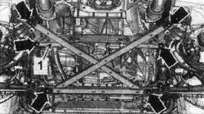
Remove the subframe cross braces. If the powertrain support, steering gear or subframe crosspiece is incorrectly installed, the vehicle must not be placed on the wheels.
The next stage of work is necessary to provide access to the elements.
Vehicles with a single-pipe exhaust system: Remove the exhaust pipe/additional muffler.
Vehicles with dual-flow exhaust system: Remove left and right additional. muffler.
All
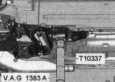
Install the "T10337" gearbox support on an engine and gearbox jack and place it underneath the gearbox. Raise the gearbox slightly.
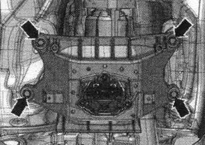
Unscrew the bolts of the tunnel cross member "arrow".
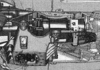
Lower the transmission using a lift by dimension "a". Dimension "a" = maximum 70 mm.
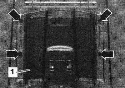
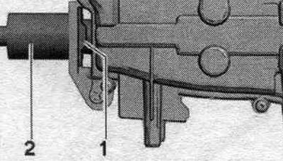
If present, remove the "arrow" nuts. Lower the underbody trim from the inside until the center tunnel heat shield "1" can be removed.
If present, remove lock washers "1" from noise insulation "2". Remove the noise insulation from the functional block "4" of the selector cable drive "3" and slide it forward.
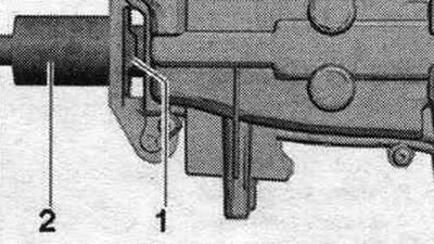
Using an 80-200 release lever, detach the ball joint "2" of the automatic transmission selector cable from the gearbox lever. Remove the retaining clip "1" and disconnect the automatic transmission selector cable from the gearbox.
Remove the retaining clip "1" from the side of the automatic transmission selector cable. Remove the selector cable drive "2" from the gearshift mechanism.
Installation
Installation in reverse order. Replace the seal. automatic transmission selector cable ring. Replace noise insulation lock washers. Before installation, lightly lubricate the loop and ball joint of the automatic transmission selector cable with Polyurea Grease -G 052142 A2-. Insert the seal. ring "1" of the automatic transmission selector cable. Insert the automatic transmission selector cable "2" into the functional unit of the gear shift mechanism "arrow". Secure the gear selector cable "2" with the locking bracket "3".
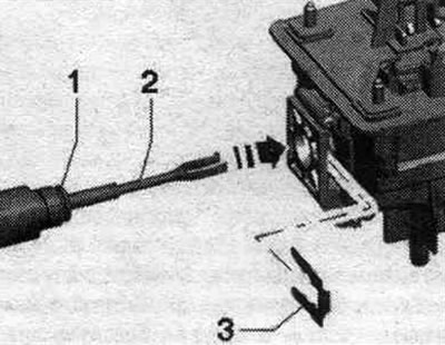
Mounting position: The curved edge of the locking bracket "1" faces the gear shift lever.
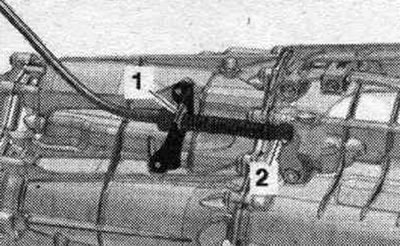
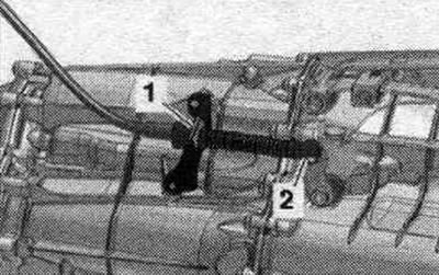
Move the shift shaft lever "1" on the gearbox all the way back "arrow" to lock the gear engagement locking mechanism. If the gear lock mechanism is locked, then both front. the wheels must not be turned in the same direction at the same time.
Press gearshift lever 3 forward with the locking pins until the gearshift is in position "D." Ensure that the automatic transmission selector lever is also in position "D." In this position, carefully insert the ball joint of selector cable "2" onto the gearshift lever. When pressing, do not deform the lever by shifting gears, as this will make precise adjustment of the selector impossible. Secure the automatic transmission selector cable with locking clamp "1".
Adjust the gear selector cable. Install the tunnel crossmember. Check the gear shift mechanism drive. Install sys. exhaust gas outlet and secure without mechanical. stresses. Install the subframe cross braces. Install diagonal braces. Install rear noise insulation.
Adjusting the gear selector cable
Pull the parking brake button to engage the electric parking brake. mechanical parking brake. Shift the automatic gearbox selector to position "D". Carefully push the selector lever gaiter sideways with the wedge "3409" "arrows" and fold it upwards. Through the hole "arrow" in the gearshift mechanism, loosen the automatic gearbox selector cable bolt 1 turn using the T40031 socket. Only loosen the clamping bolt — do not unscrew it. The clamp bolt is only accessible in the "D" position. With the clamp bolt loosened, the automatic transmission selector lever should remain in the "D" position. Carefully move the automatic transmission selector lever back and forth, avoiding any other shift positions. This will loosen the selector cable. Move the automatic transmission selector to the "Tiptronic" slot. In this position, tighten the clamp bolt using the "T40031" socket wrench, without touching the automatic transmission selector. Check the gearshift mechanism drive. After adjusting the gear selector cable, perform the corresponding "Guided Function" using a diagnostic tester. If the automatic transmission selector cable does not function properly after adjusting it, return the selector cable to its default setting.
[The original article is available on the online resource «AudiManual»]