
Repair Chevrolet Repair Toyota Repair Honda Repair AvtoVAZ Repair Mercedes-Benz Repair BMW Repair Opel
Home  |  Contacts  |  Sitemap  |    
English Русский
Български
Беларускі
Український
Српски
Hrvatski
Română
Polski
Slovenský
Magyar
AudiManual.ru


  • AUDI 80
  • AUDI 100
  • AUDI A3
  • AUDI A4
  • AUDI A6
  • AUDI A8
  • AUDI Q
  • OTHER
  • ARTICLES
B8 (2007-2015) B7 (2004-2008) B6 (2000-2006) B6 (2000-2006, petrol) B5 (1994-2001) B5 (1994-2001, petrol)

Automatic transmission selector handle, automatic transmission selector position indicator panel «Y26» (Audi A4 B8)

  • Home
  • Audi A4
  • B8 (2007-2015)
  • Transmission
  • Automatic transmission 0B5
  • Automatic transmission selector handle, automatic transmission selector position indicator panel «Y26»
            0

Automatic transmission selector handle, automatic transmission selector position indicator panel "Y26"
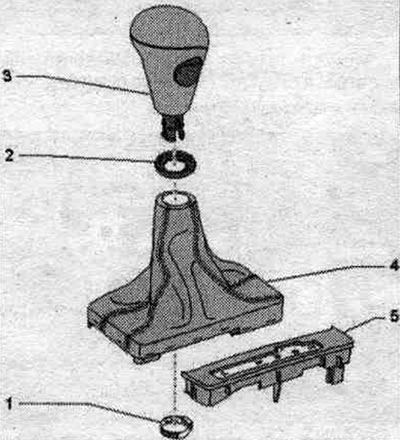


1. Clamp: for securing the handle to the automatic transmission selector; replace.

1. Clamp: for securing the handle to the automatic transmission selector; replace.
2. Decorative rosette.
3. Selector handle.
4. Selector cuff.
5. Gear selector position indicator panel "Y26".


Removal


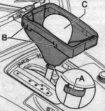
Pull the parking brake button to engage the electric parking brake. mechanical parking brake. Shift the selector to the "N" position. The automatic transmission selector handle is removed along with the selector sleeve. Carefully press the selector lever cuff from the side using wedge "3409" "arrow" and turn it upwards.
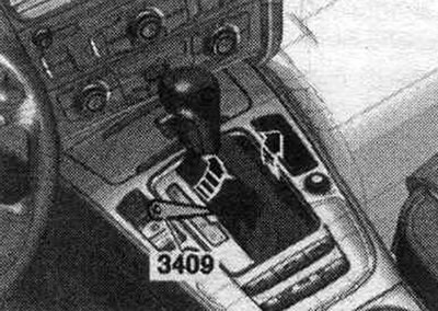
Pull the parking brake button to engage the electric parking brake. mechanical parking brake. Shift…


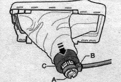
Provide the cable connector with the locking button in the extended "Arrow" position, as shown in the figure.
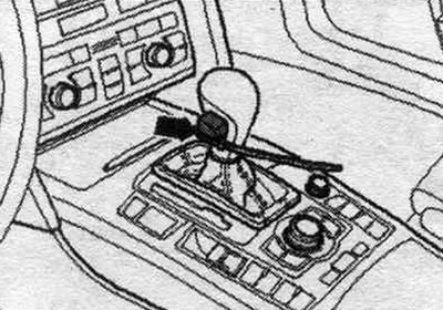


Provide the cable connector with the locking button in the extended «Arrow» position, as shown in…


Place the gearshift lever boot "1" onto the top of the gear selector lever "2". Disconnect the clamp "arrow" and remove the selector handle together with the selector boot, without pressing the locking button.
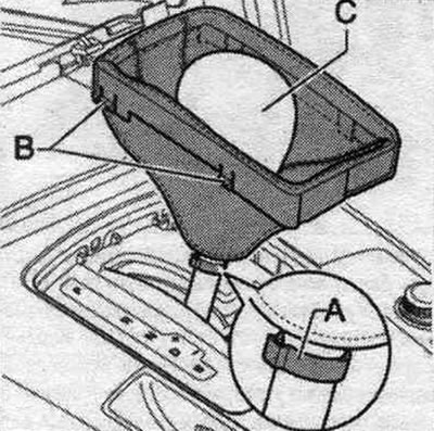
Place the gearshift lever boot «1» onto the top of the gear selector lever «2». Disconnect the…


Installation


To install the automatic transmission selector handle, the locking button must be pulled out as far as it will go and secured using an arrow-shaped cable tie or the mounting tool supplied with the new handle. If, due to an oversight, the locking button was not fixed, it cannot be removed from the automatic transmission selector handle using the mechanical tool. auxiliary tool. Place the compressed air gun underneath the handle and press the locking button with compressed air.


To install the automatic transmission selector handle, the locking button must be pulled out as far…


Place the new "arrow" clamp onto the selector handle. Place the automatic transmission selector handle completely onto the selector lever, with the locking button facing the driver. The handle should fit into the annular groove of the automatic transmission selector lever. Remove the cable tie or mounting hardware. device, whereby the drive of the locking button enters the vertical groove of the selector. If necessary, press the locking button into the selector handle. To check the operation of the button mechanism, move the selector lever to the "R" and "S" positions. If the selector cannot be moved to these positions, the handle must be removed again. Secure the automatic transmission selector handle "2" to the automatic transmission selector lever with the "arrow" clamp. Use the "VAG 1275" hose clamp pliers to do this. Secure the automatic transmission selector sleeve retainer frame "1" to the center console.

Separating the automatic transmission selector sleeve from the selector handle


Remove the automatic transmission lever handle. Tie the spring tabs "1" of the selector handle together with a cable tie "3", as shown in the figure. Slide the selector sleeve "2" through the spring tab retainers "arrow." Remove the cable tie and remove the sleeve and sleeve from the selector.


Remove the automatic transmission lever handle. Tie the spring tabs «1» of the selector handle…


Installation is in reverse order, the longer side of the automatic transmission selector cuff frame faces the driver. Install the automatic transmission lever handle.
The article was checked by auto expert Timur Bazhenov
This article is available at russian, bulgarian, belarusian, ukrainian, serbian, croatian, romanian, polish, slovak, hungarian

Share information:
Previous articles
Audi A4 B8: Automatic transmission 0B5
Next articles

Gear shift mechanism — removal and installation
Electrical and electronic components and their locations
Flywheel and dual clutch
Gearbox markings and reference data on oil volume
Removal and installation the gear selector cable
Removal the gearbox — vehicles with a 4-cylinder petrol engine
Removal the gearbox — vehicles with a 6-cylinder petrol engine
Gearbox removal — vehicles with a 6-cylinder TDI engine


Similar articles on other Audi car models:
Vacuum Pump (with Automatic Transmission) — Removal and… Audi 80 B3 (1986-1991, petrol)
Automatic transmission selector Audi 100 C3 (1982-1990, petrol)
Adjusting the Automatic Transmission Shift Selector Cable Audi A3 Type 8L (1996-2003)
Checking the automatic transmission fluid level Audi A6 C4 (1994-1997)
Automatic transmission selector Audi A8 D2 (1994-2002)
Automatic transmission selector handle, automatic transmission… Audi Q5 Type 8R (2008-2017)
Removal and installation the automatic transmission selector… Audi A2 (1999-2005)
Link to this page in different formats


Visitor comments

No comments yet


How much will 26 + 44 =


A4(B8, 2007-2015) 
  • General information
  • Operating instructions
  • Power unit
  • Petrol engines 1.8 l
  • Petrol engines 1.8/2.0 l
  • Petrol engines 3.0 l
  • Petrol engines 3.2 l
  • Fuel system (petrol)
  • Diesel engines 2.0 l (CA*)
  • Diesel engines 2.0 l (CJCB)
  • Diesel engines 2.7/3.0 l
  • Diesel engines 3.0 l
  • Fuel system (diesel)
  • Transmission
  • Manual gearbox 0B1
  • Manual gearbox 0B2
  • Manual gearbox 0B3
  • Manual gearbox 0B4
  • Automatic transmission 0B5
  • Automatic transmission 0B6
  • Automatic transmission 0AW
  • All-wheel drive system
  • Chassis
  • Front suspension
  • Rear suspension
  • Brake system
  • Steering system
  • Body
  • Exterior
  • Interior
  • Seats
  • Doors, locks and windows
  • Security system
  • Heating and air conditioning
  • Electrical equipment
  • Audio system
  • Power devices
  • Equipment and devices
  • Lighting and lamps
  • Electrical circuits
 
A4(B7, 2004-2008) 
  • General information
  • Introduction to manual
  • Troubleshooting
  • Operating instructions
  • Maintenance
  • Power unit
  • Petrol engines 2.0 (ALT)
  • Petrol engines 2.0 (TFSI)
  • Petrol engines 1.8 (MPI)
  • Diesel engines
  • Cooling system
  • Air conditioner
  • Fuel and exhaust system
  • Ignition system
  • Starting and charging
  • Transmission
  • Clutch
  • Manual gearbox
  • Automatic gearbox
  • Drive shafts
  • Chassis
  • Brake system
  • Front suspension
  • Rear suspension
  • Steering
  • Body
  • Exterior
  • Interior
  • Electrical equipment
  • Equipment and devices
  • Lighting and signaling
  • Windscreen wipers and washers
  • Electrical diagrams
  • Electrical diagrams (since 2007)
 
A4(B6, 2000-2006) 
  • General information
  • Vehicle Description
  • User manual
  • Maintenance
  • Power unit
  • Gasoline engine
  • Diesel engine
  • Lubrication system
  • Cooling system
  • Supply system
  • Injection system
  • Exhaust system
  • Ignition and control
  • Transmission
  • Gear box
  • Clutch and drive shafts
  • Chassis
  • Brake system
  • Car suspension
  • Steering
  • Body
  • Heating and ventilation
  • Exterior (external elements)
  • Interior (internal elements)
  • Electrical equipment
  • Power devices
  • Lighting and appliances
  • Electrical circuits
 
A4(B6, 2000-2006, petrol) 
  • General information
  • Introduction to the guide
  • Car care
  • Power unit
  • Engine repair
  • Lubrication system
  • Cooling system
  • Injection and control system
  • Ignition system
  • Power and exhaust system
  • Transmission
  • Clutch and drive shafts
  • Car gearbox
  • Chassis
  • Suspension and wheels
  • Steering
  • Brake system
  • Body
  • Interior
  • Exterior
  • Electrical equipment
  • Equipment and devices
  • Lighting and signaling
  • Power devices
  • Electrical circuits
 
A4(B5, 1994-2001) 
  • General information
  • Introduction to the guide
  • Car care
  • Maintenance (gasoline)
  • Maintenance (diesel)
  • Power unit
  • Gasoline engines
  • Diesel engines
  • Engine overhaul
  • Cooling system
  • Fuel injection (gasoline)
  • Fuel system (diesel)
  • Exhaust system
  • Ignition system
  • Transmission
  • Clutch
  • Mechanical gearbox
  • Automatic gearbox
  • Drive shafts
  • Chassis
  • Brake system
  • Car suspension
  • Steering
  • Body
  • Exterior
  • Interior
  • Doors, locks and windows
  • Heating and ventilation
  • Electrical equipment
  • Power devices
  • Equipment and devices
  • Electrical circuits
 
A4(B5, 1994-2001, petrol) 
  • General information
  • Vehicle description
  • Maintenance
  • Power unit
  • Engine repair
  • Turbocharging
  • Exhaust system
  • Cooling system
  • Ignition system
  • Fuel system
  • Motronic injection system
  • MPI and MPFI injection system
  • Transmission
  • Clutch
  • Gearbox and shafts
  • Chassis
  • Steering
  • Car suspension
  • Brake system
  • Wheels and tires
  • Body
  • Heating and ventilation
  • Body parts
  • Electrical equipment
  • Fuses and relays
  • Power devices
  • Lighting and lamps
  • Tools and devices
  • Electrical circuits
 
AudiManual.ru © 2017-2026 · Mobile version · Feedback · Sitemap: EN BG BY UA RS HR RO PL SK HU · Site search · News and articles
80 B2 · 80 B3 petrol · 80 B3 · 80 B4 · 100 C3 diesel · 100 C3 petrol · 100 C3 · 100 C4 petrol · 100 C4 · A3 Type 8L · A4 B5 petrol · A4 B5 · A4 B6 petrol · A4 B6 · A4 B7 · A4 B8 · A6 C4 · A6 C5 · A6 C5 Allroad · A8 D2 · Q5 Type 8R · Q7 Typ 4L · Audi A2 ·
This site uses cookies 🍪. Click the button to accept this fact.