Repair Chevrolet Repair Toyota Repair Honda Repair AvtoVAZ Repair Mercedes-Benz Repair BMW Repair Opel
Home  |  Contacts  |  Sitemap  |    
English Русский
Български
Беларускі
Український
Српски
Hrvatski
Română
Polski
Slovenský
Magyar
AudiManual.ru


  • AUDI 80
  • AUDI 100
  • AUDI A3
  • AUDI A4
  • AUDI A6
  • AUDI A8
  • AUDI Q
  • OTHER
  • ARTICLES
B8 (2007-2015) B7 (2004-2008) B6 (2000-2006) B6 (2000-2006, petrol) B5 (1994-2001) B5 (1994-2001, petrol)

Flywheel and dual clutch (Audi A4 B8)

  • Home
  • Audi A4
  • B8 (2007-2015)
  • Transmission
  • Automatic transmission 0B5
  • Flywheel and dual clutch
            0
Table of contents: Flywheel and dual clutch ↓ Removal and installation the flywheel ↓ Removal and installation a dual… ↓

Flywheel and dual clutch
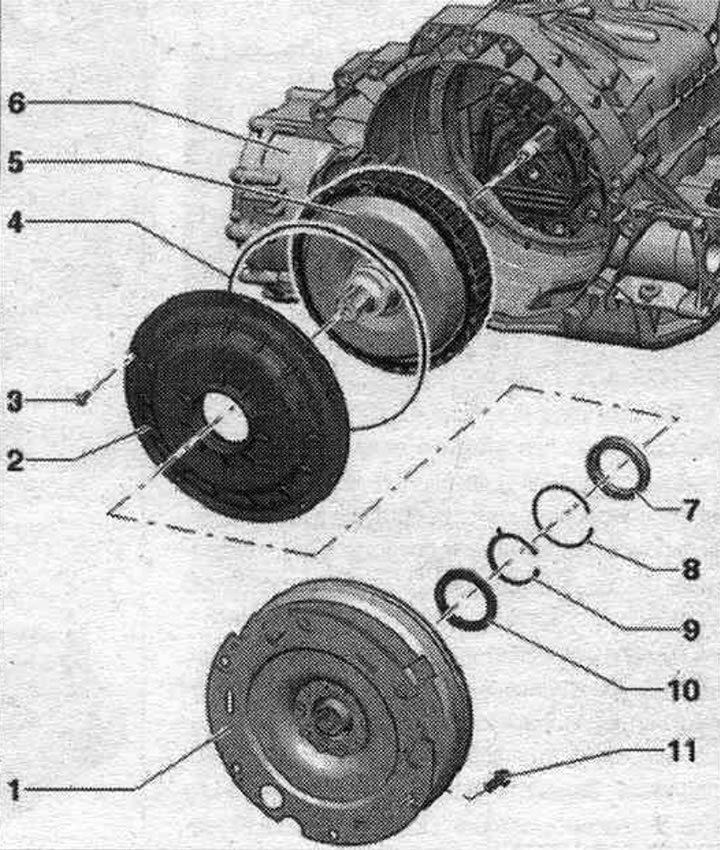


1. Flywheel.

1. Flywheel.
2. Coupling cover.
3. Bolt.
4. Sealing ring: replace.
5. Double clutch: After replacing the double clutch, the corresponding "Guided Function" should be carried out using a diagnostic tester.
6. Carter KP.
7. Double clutch ball bearing.
8. Retaining ring: for ball bearing; replace.
9. Retaining ring: double clutch; replace.
10. Drive shaft sealing ring.
11. Bolt: replace; 3 pcs. in 4-cylinder engines; 6 pcs. in 6-cylinder engines; 60 Nm.


Torque and sequence, tightening for dual clutch and clutch cover


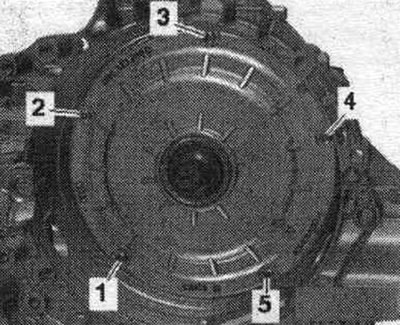
Tighten the bolts in sequence. "1...5" in 3 stages.
1. Tighten evenly by hand until the bolt head is pressed against the clutch cover.

1. Tighten evenly by hand until the bolt head is pressed against the clutch cover.
2. Tighten in 90° increments until the clutch cover is flush with the gearbox housing.
3. Tighten to 8 Nm.


Removal and installation the flywheel


The gearbox is secured to the engine and gearbox retainer "VAS 6095". Remove the left shaft with flange. Secure the puller "T40176" to the flywheel "A" with the nut "B" "arrow".
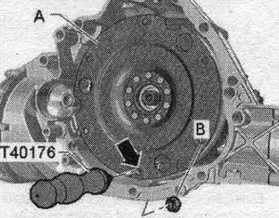
The gearbox is secured to the engine and gearbox retainer «VAS 6095». Remove the left shaft with…


Rotate the "T40176" puller upward. To prevent the flywheel from tipping over, hold it from below, as shown in the figure. Remove the flywheel without tilting it from the drive shaft "arrow".
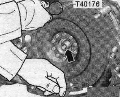
Rotate the «T40176» puller upward. To prevent the flywheel from tipping over, hold it from below,…


Installation


Installation in reverse order, thoroughly clean the gearbox housing in the differential access area "arrow A" and the shaft sealing ring "arrow B". If the shaft sealing ring between the differential and the gearbox housing "arrow B" is damaged, replace it.
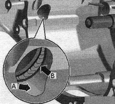
Installation in reverse order, thoroughly clean the gearbox housing in the differential access area…


Fill the space between the working edge and the shooter's boot halfway with sealant. Clean the drive shaft "arrow". Lubricate the drive shaft splines with a thin layer of clutch driven disc spline grease -G 000 100-.
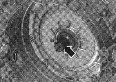


Fill the space between the working edge and the shooter's boot halfway with sealant. Clean the…


Carefully, without allowing it to tilt, install the flywheel onto the "arrow" drive shaft. Unscrew the "T40176" puller from the "A" flywheel. Install the left shaft with the flange.

Removal and installation a dual clutch


The gearbox is secured to the engine and gearbox holder "VAS 6095". Remove the flywheel. Drain the ATF. Remove the drive shaft seal using the T20143/2 hook.
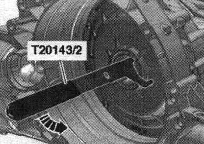
The gearbox is secured to the engine and gearbox holder «VAS 6095». Remove the flywheel. Drain the…


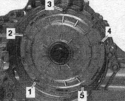
Unscrew screws "1...5".

Unscrew screws «1...5».


Rotate the gearbox in the VAS 6095 tilter in a vertical plane. Place the "T40123 A/1" sleeve onto the drive shaft. Attach the ATF pump drive puller "T40123 A" to the drive shaft. The "arrow" edge of the ATF pump puller should fit under the "T40123 A/1" bushing. Close the puller and tighten the knurled nut "1" (approx. 20 Nm). Check the tightness of the ATF pump puller on the drive shaft.
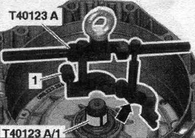


Rotate the gearbox in the VAS 6095 tilter in a vertical plane. Place the «T40123 A/1» sleeve onto…


Connect the ATF pump puller "T40123 A" to the additional hook "10-222 A/2" and hang it on the "VAS 6100" crane. Carefully remove the dual clutch from the gearbox housing.
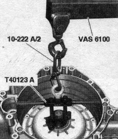
Connect the ATF pump puller «T40123 A» to the additional hook «10-222 A/2» and hang it on the «VAS…


Place the double clutch with the cover on a soft surface, avoiding damage to the thin spacer "arrow A".
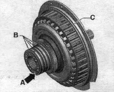
Place the double clutch with the cover on a soft surface, avoiding damage to the thin spacer «arrow…


Remove the "arrow" retaining ring with pliers.
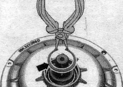


Remove the «arrow» retaining ring with pliers.


Remove clutch cover "2" from clutch "1".
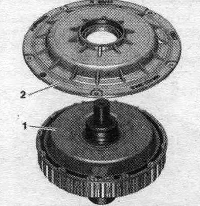
Remove clutch cover «2» from clutch «1».


If the clutch cover does not come off, lightly tap the drive shaft with a plastic mallet while the second mechanic lifts the clutch cover manually. In this case, avoid damaging the thin spacer "arrow A".

Installation


Installation in reverse order. Replace the washer and snap ring. Clean the sealing surface on the clutch housing cover. Turn the rectangular section ring "B" on the hub, make sure it moves freely and check the axial clearance. If the movement of the rectangular ring is difficult, the double clutch cannot be installed. Clean the gearbox housing in the area of the double clutch and the sealing surface. Screw the centering tool "T40199" into the threaded holes of the gearbox housing, as shown in the figure
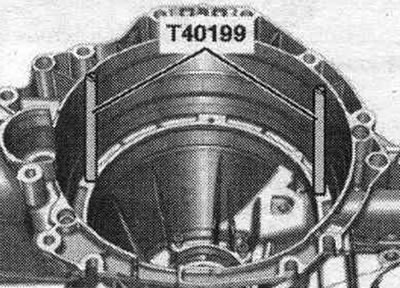


Installation in reverse order. Replace the washer and snap ring. Clean the sealing surface on the…


Check the "arrow" thread in the gearbox for signs of wear.
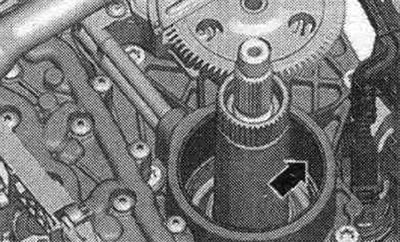
Check the «arrow» thread in the gearbox for signs of wear.


Wet the seal. the "C" ring and "B" hub of the dual clutch are replaced when changing the ATF oil. Insert the dual clutch into the gearbox housing as shown in the figure, using short turns and longitudinal movements to engage the drive shaft between the ATF pump and the gearbox shafts. The dual clutch is installed correctly when the O-ring on the clutch cover fits snugly against the edge of the gearbox housing. Be careful not to pinch the new O-ring during installation. Strictly observe the order. tightening the dual clutch bolts and clutch cover. Replace the seal. drive shaft ring. Install the flywheel. After installing the transmission, add ATF. After replacing the dual clutch, perform the appropriate "Guided Function" using a diagnostic tester.
The article was checked by auto expert Timur Bazhenov
This article is available at russian, bulgarian, belarusian, ukrainian, serbian, croatian, romanian, polish, slovak, hungarian

Share information:
Previous articles
Audi A4 B8: Automatic transmission 0B5
Next articles

Gearbox markings and reference data on oil volume
Electrical and electronic components and their locations
Gear shift mechanism — removal and installation
Automatic transmission selector handle, automatic transmission…
Removal and installation the gear selector cable


Similar articles on other Audi car models:
Flywheel/Drive Disc — Removal, Inspection and Installation Audi 80 B3 (1986-1991, petrol)
Flywheel/Drive Disc — Removal, Inspection and Installation Audi 100 C3 (1982-1990, diesel)
Changing the oil in the Haldex clutch of all-wheel drive models Audi A3 Type 8L (1996-2003)
Clutch drive disc Audi A6 C5 (1997-2004)
Dual mass flywheel Audi A8 D2 (1994-2002)
Flywheel and dual clutch Audi Q5 Type 8R (2008-2017)
Sealing flanges and dual mass flywheel Audi A2 (1999-2005)
Link to this page in different formats


Visitor comments

No comments yet


How much will 27 + 11 =


A4(B8, 2007-2015) 
  • General information
  • Operating instructions
  • Power unit
  • Petrol engines 1.8 l
  • Petrol engines 1.8/2.0 l
  • Petrol engines 3.0 l
  • Petrol engines 3.2 l
  • Fuel system (petrol)
  • Diesel engines 2.0 l (CA*)
  • Diesel engines 2.0 l (CJCB)
  • Diesel engines 2.7/3.0 l
  • Diesel engines 3.0 l
  • Fuel system (diesel)
  • Transmission
  • Manual gearbox 0B1
  • Manual gearbox 0B2
  • Manual gearbox 0B3
  • Manual gearbox 0B4
  • Automatic transmission 0B5
  • Automatic transmission 0B6
  • Automatic transmission 0AW
  • All-wheel drive system
  • Chassis
  • Front suspension
  • Rear suspension
  • Brake system
  • Steering system
  • Body
  • Exterior
  • Interior
  • Seats
  • Doors, locks and windows
  • Security system
  • Heating and air conditioning
  • Electrical equipment
  • Audio system
  • Power devices
  • Equipment and devices
  • Lighting and lamps
  • Electrical circuits
 
A4(B7, 2004-2008) 
  • General information
  • Introduction to manual
  • Troubleshooting
  • Operating instructions
  • Maintenance
  • Power unit
  • Petrol engines 2.0 (ALT)
  • Petrol engines 2.0 (TFSI)
  • Petrol engines 1.8 (MPI)
  • Diesel engines
  • Cooling system
  • Air conditioner
  • Fuel and exhaust system
  • Ignition system
  • Starting and charging
  • Transmission
  • Clutch
  • Manual gearbox
  • Automatic gearbox
  • Drive shafts
  • Chassis
  • Brake system
  • Front suspension
  • Rear suspension
  • Steering
  • Body
  • Exterior
  • Interior
  • Electrical equipment
  • Equipment and devices
  • Lighting and signaling
  • Windscreen wipers and washers
  • Electrical diagrams
  • Electrical diagrams (since 2007)
 
A4(B6, 2000-2006) 
  • General information
  • Vehicle Description
  • User manual
  • Maintenance
  • Power unit
  • Gasoline engine
  • Diesel engine
  • Lubrication system
  • Cooling system
  • Supply system
  • Injection system
  • Exhaust system
  • Ignition and control
  • Transmission
  • Gear box
  • Clutch and drive shafts
  • Chassis
  • Brake system
  • Car suspension
  • Steering
  • Body
  • Heating and ventilation
  • Exterior (external elements)
  • Interior (internal elements)
  • Electrical equipment
  • Power devices
  • Lighting and appliances
  • Electrical circuits
 
A4(B6, 2000-2006, petrol) 
  • General information
  • Introduction to the guide
  • Car care
  • Power unit
  • Engine repair
  • Lubrication system
  • Cooling system
  • Injection and control system
  • Ignition system
  • Power and exhaust system
  • Transmission
  • Clutch and drive shafts
  • Car gearbox
  • Chassis
  • Suspension and wheels
  • Steering
  • Brake system
  • Body
  • Interior
  • Exterior
  • Electrical equipment
  • Equipment and devices
  • Lighting and signaling
  • Power devices
  • Electrical circuits
 
A4(B5, 1994-2001) 
  • General information
  • Introduction to the guide
  • Car care
  • Maintenance (gasoline)
  • Maintenance (diesel)
  • Power unit
  • Gasoline engines
  • Diesel engines
  • Engine overhaul
  • Cooling system
  • Fuel injection (gasoline)
  • Fuel system (diesel)
  • Exhaust system
  • Ignition system
  • Transmission
  • Clutch
  • Mechanical gearbox
  • Automatic gearbox
  • Drive shafts
  • Chassis
  • Brake system
  • Car suspension
  • Steering
  • Body
  • Exterior
  • Interior
  • Doors, locks and windows
  • Heating and ventilation
  • Electrical equipment
  • Power devices
  • Equipment and devices
  • Electrical circuits
 
A4(B5, 1994-2001, petrol) 
  • General information
  • Vehicle description
  • Maintenance
  • Power unit
  • Engine repair
  • Turbocharging
  • Exhaust system
  • Cooling system
  • Ignition system
  • Fuel system
  • Motronic injection system
  • MPI and MPFI injection system
  • Transmission
  • Clutch
  • Gearbox and shafts
  • Chassis
  • Steering
  • Car suspension
  • Brake system
  • Wheels and tires
  • Body
  • Heating and ventilation
  • Body parts
  • Electrical equipment
  • Fuses and relays
  • Power devices
  • Lighting and lamps
  • Tools and devices
  • Electrical circuits
 
AudiManual.ru © 2017-2026 · Mobile version · Feedback · Sitemap: EN BG BY UA RS HR RO PL SK HU · Site search · News and articles
80 B2 · 80 B3 petrol · 80 B3 · 80 B4 · 100 C3 diesel · 100 C3 petrol · 100 C3 · 100 C4 petrol · 100 C4 · A3 Type 8L · A4 B5 petrol · A4 B5 · A4 B6 petrol · A4 B6 · A4 B7 · A4 B8 · A6 C4 · A6 C5 · A6 C5 Allroad · A8 D2 · Q5 Type 8R · Q7 Typ 4L · Audi A2 ·
This site uses cookies 🍪. Click the button to accept this fact.