



Table of contents: Gear shift mechanism ↓ Checking the gear shift mechanism ↓ Emergency release of the gearshift… ↓ Removal and installation the gear… ↓ All ↓
Gear shift mechanism
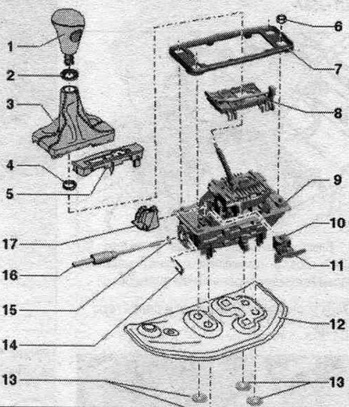
1. Selector handle.
2. Decorative rosette.
3. Selector cuff.
4. Clamp.
5. Gear selector position indicator panel "Y26".
6. Nut: for securing the shift drive to the body; 4 pcs., 10 Nm.
7. Gasket.
8. Control unit for automatic transmission selector sensors "J587" with Tiptronic switch "F189".
9. Gearshift mechanism functional unit: replace only as an assembly; after removing and installing the shift drive functional unit, it is necessary to perform the corresponding "Guided Function" using a diagnostic tester.
10. Selector lever lock solenoid -N 110-.
11. Selector position switch P "F305": consists of 2 reed switches on the board of the selector lock magnet of the automatic transmission "N110"; replacement is only possible together with the automatic transmission selector lock magnet "N110".
12. Soundproofing: not installed on all vehicles.
13. Lock washers: replace, 4 pcs.; for attaching noise insulation to the functional block of the switching mechanism.
14. Locking clamp: secures the automatic transmission selector cable to the shift mechanism functional block.
15. Sealing ring: replace.
16. Gear selector cable: do not bend or kink.
17. Cover: above the selector lock solenoid "N110".
Checking the gear shift mechanism
1. Checking the operation of the gear shift mechanism drive
When the automatic transmission selector is in position "S", "D", "R" the starter does not engage in the Tiptronic slot. At speeds above 5 km/h and when the automatic transmission selector is shifted to the "N" position, the solenoid does not lock the automatic transmission selector. The selector may be in one gear position. When moving the automatic transmission selector to the "N" position at a speed of less than 2 km/h (the car is practically standing still), the selector lock solenoid should only activate after approximately 1 second. The selector lever should only be released from the "N" position when the brake pedal is depressed.
Gear selector in position "P": Pull the parking brake button to engage the electric parking brake. mechanical parking brake. Do not press the brake pedal. To switch to the "Ignition on" position, briefly press the key in the ignition switch. Do not press the brake pedal.
The automatic transmission selector is locked and cannot be moved out of position "P" while the locking button on the selector handle is pressed. The automatic transmission selector lock solenoid "N110" locks the selector. Press and hold the brake pedal. The automatic transmission selector lock solenoid "N110" releases the selector lock. It is now possible to set the selector to the driving position. With the locking button on the automatic transmission selector handle pressed, slowly shift the selector sequentially from "P" and further "R, N, D, S"; in this case, check that the indication of the automatic transmission selector position "Y6" in the instrument cluster corresponds to the actually selected gear. The automatic transmission selector is in position "N" and the ignition is on: do not press the brake pedal. After some time, the selector is locked and, despite pressing the locking button on the automatic transmission selector handle, it cannot be moved out of the "N" position. The "N110" automatic transmission selector lock solenoid locks the selector. Press the brake pedal. The automatic transmission selector lock solenoid "N110" releases the selector lock. The "D" position may be engaged. With the automatic transmission selector in the "D" position and the ignition on, move the automatic transmission selector to the "Tiptronic" position. The illuminated "D" symbol on the "Y26" automatic transmission selector position indicator panel should go out, and the "+" and "-" symbols should light up.
The Y6 automatic transmission selector position indicator on the instrument cluster should change from "D" to "M1" when the selector is moved to the Tiptronic position. If the specified values are not achieved, perform Guided Fault Finding using a diagnostic tester. Adjust the gear selector cable. Check the locking button on the selector handle. Check the key lock in the ignition switch.
2. Checking the key lock in the ignition switch
Pull the parking brake button to engage the electric parking brake. mechanical parking brake. Do not press the brake pedal. To switch to the "Ignition on" position, briefly press the key in the ignition switch. Press and hold the brake pedal. The automatic transmission selector can only be moved from the "P" position when the locking button on the selector handle is pressed. Turn off the ignition. The ignition key must not be removed in any of the automatic transmission selector positions other than "P". Move the selector lever to position "P". Remove the ignition key. Remove the ignition key only when the selector is in position "P". The selector cannot be moved from the "P" position if the lock button and the foot brake pedal are pressed. If the ignition key removal interlock does not operate as described, perform Guided Fault Finding with a diagnostic tester.
3. Checking the locking button on the gear selector handle
Check the smooth operation of the locking button. The lock button should be pressed without much force. After releasing the button, it should automatically and completely return to its original position. If the specified values are not achieved, check that the selector handle is correctly installed. Check that the selector lever is not bent.
Checking the work
The ignition is on. The locking button on the automatic transmission selector handle must be pressed for the following shifts; or, if the locking button is not pressed, the selector should not move to the specified position: "P" after "R" and press the brake pedal, "D" after "S", "N" after "R"; when stopping, after a long wait add. press the brake pedal, "R" after "P". If the specified values are not achieved, check the correct installation of the selector handle. Perform a guided troubleshooting on the diagnostic system and check the N110 gear selector lock magnet. Adjust the gear selector cable.
Emergency release of the gearshift mechanism
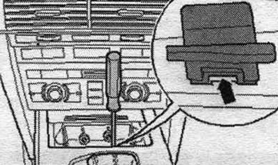
If the battery is disconnected or discharged, the automatic transmission selector cannot be moved out of the "P" position. The vehicle cannot be moved or towed. When the emergency release is activated, the electromagnet of the automatic transmission selector lock "N110" releases the lock even in a de-energized state. Remove the front ashtray insert. Use a screwdriver to pry off the cover of the "arrow" ashtray housing. The shape of the cover may differ from the one shown in the picture.
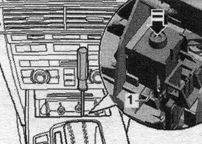
Using a screwdriver, gently press the "arrow" cylinder onto the "N110" automatic transmission selector lock magnet in the center hole in the ashtray housing. While holding down the locking button on the selector, simultaneously move the selector from position "P." This unlocks the automatic transmission selector in position "P" with locking lever "1." If the "arrow" cylinder of the "N110" automatic transmission selector lock magnet is hidden by a noise-insulating shield or cable, these must be moved to the side.
Removal and installation the gear shift module functional unit
Remove the front ashtray.
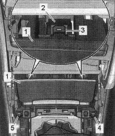
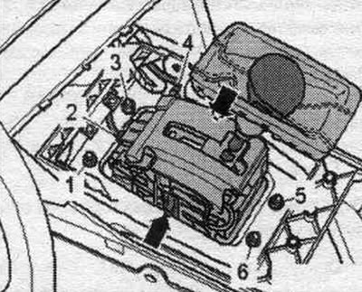
Disconnect plug connectors "2" and "4". The damping mat is not shown in the figure. Remove the damping mat above the gear shift mechanism. Unscrew the bolts "1, 3, 5, 6".
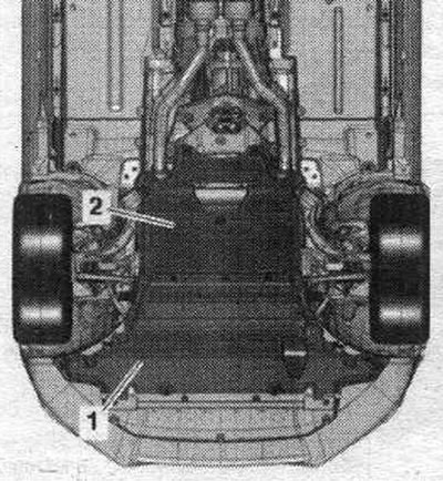
Remove sound insulation "1" and "2".
Vehicles with 4-cyl. petrol, engine: Remove the exhaust pipe/ext. muffler.
Cars with 6-cyl. petrol engine: Remove the additional muffler on the right.
Vehicles with 6-cyl. TDI engine: Remove exhaust pipe.
All
Remove the subframe cross braces. If the power unit support is installed incorrectly. it is prohibited to place the steering gear or the vehicle subframe spacer crosspiece on the wheels.
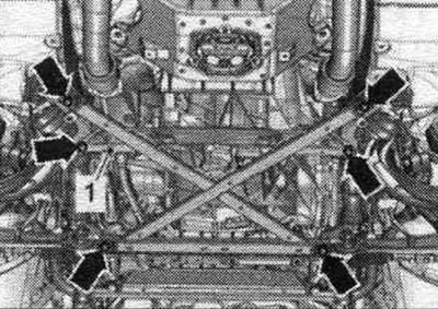
If present, unscrew the "arrow" bolts and remove the heat shield "1" of the propeller shaft.
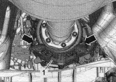
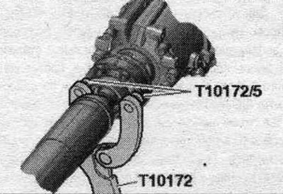
Car with a bolted driveshaft: Unscrew the bolts connecting the driveshaft to the gearbox, while holding it from turning using the counter support "T10172" with "T10172/5". Move the driveshaft towards the rear final drive; constant velocity joints are movable in the axial direction. Place the driveshaft on the front crossmember.
Vehicles with a plug-in cardan shaft: Use the vehicle data plate or the marking on the rear final drive to determine the type of rear final drive installed. Remove the cardan shaft (insert).
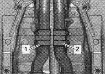
Vehicles with 6-cyl. petrol engine: Loosen the mounting sleeve "1", move it back and secure the left part of the add. muffler on the body. "Pos. 2" should not be taken into account.
All
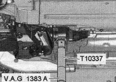
Install the "T10337" gearbox support on an engine and gearbox jack and place it underneath the gearbox. Raise the gearbox slightly.
Unscrew the bolts of the tunnel cross member "arrow".
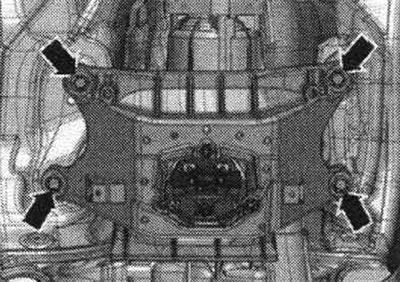
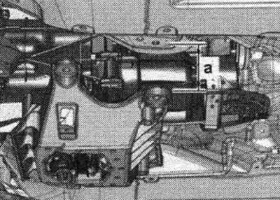
Lower the gearbox using the engine and gearbox lift -VAG 1383 A- by dimension "a". Dimension "a" = maximum 70 mm.
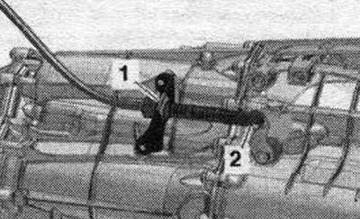
Using an 80-200 release lever, detach the ball joint "2" of the automatic transmission selector cable from the gearbox lever. Remove the retaining clip "1" and disconnect the automatic transmission selector cable from the gearbox.
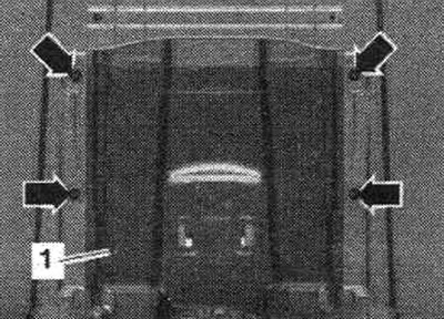
If present, unscrew the "arrow" nuts. Lower the bottom trim from the inside as follows. so that the heat shield "1" of the central tunnel can be removed. Remove the gear shift mechanism.
Installation
Installation in reverse order. Before installation, lightly lubricate the ball joint of the selector cable with polyurea grease -G 052142 A2-. The selector cable must not be bent or broken. Adjust the gear selector cable. Install the heat shield. Install the tunnel crossbar. Check the gear shift mechanism drive. Use the vehicle data plate or the rear final drive marking to determine the type of rear final drive installed. Install the cardan shaft. Install sys. exhaust gas outlet and secure without mechanical. stresses. Install the subframe cross braces. Install diagonal braces. Install rear noise insulation. Install the front ashtray. After removing and installing the shift actuator functional unit, it is necessary to perform the corresponding "Guided Function" using a diagnostic tester.