Removal: Set the front wheels to the straight-ahead position. Turn off the ignition. Disconnect the ground wire "2" from the battery terminal.
A/m with hydraulics. power steering: Pump out the hydraulic power steering oil using a device for pumping oil out of the expansion tank. tank "3". "Pos. 1, 2, 4" should not be taken into account.
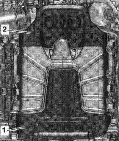
Vehicle with 3.2 l FSI engine: Remove the rear engine cover "upper arrows".
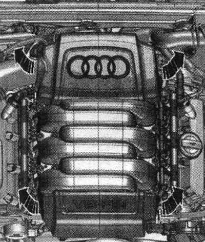
Vehicles with 3.0 l TFSI engine: Remove engine covers "1" and "2" upwards.
All
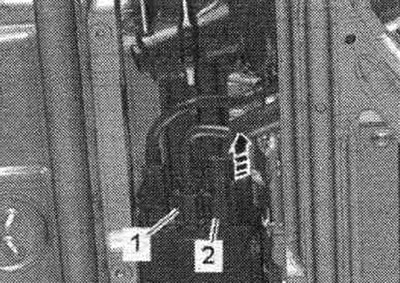
Remove the front wheels. Remove cover "1" of the drive shaft in the wheel arch on the left and right.
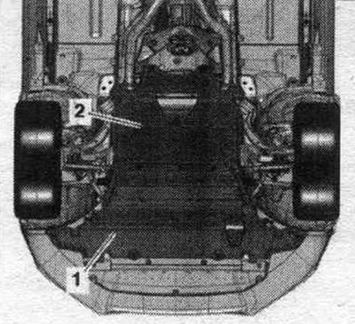
Remove sound insulation "1" and "2".
Remove the left and right add. muffler.
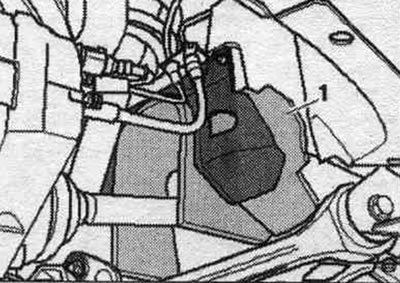
Unscrew the nuts "arrows" and bolts "1", remove the right catalytic converter from the exhaust manifold and press it to the right.
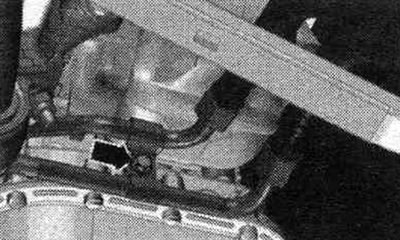
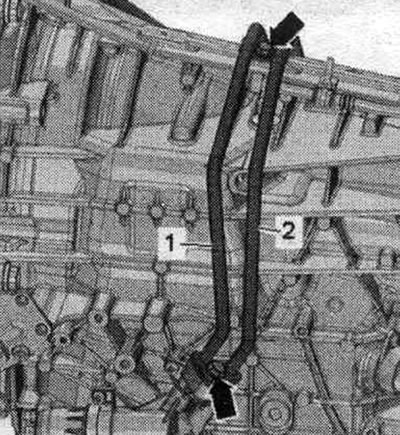
Remove the ATF line arrow bolts. Remove the front wall of the water drain box.
Vehicles with an ATF line filter: Loosen the bolts "arrows" and disconnect the ATF line "1" from the gearbox. Ignore "Pos. 2, 3".
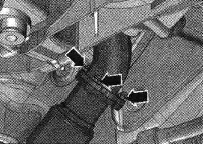
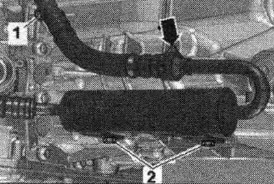
Remove bolt "1." Disconnect the ATF line from the ATF line filter by removing the clamp "arrow." Ignore "Pos. 2.".
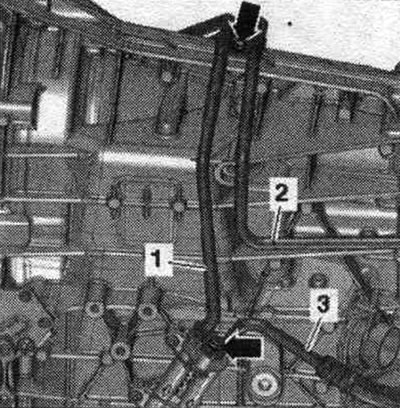
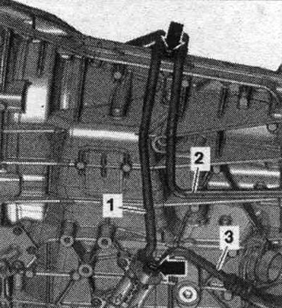
Tie up ATF lines "1" and "2". Ignore "Pos. 3". Close open lines and pipes with clean plugs from the "VAS 6122" engine plug set.
Cars with a replaceable ATF filter: Unscrew the bolts "arrows", disconnect the ATF lines "1, 2" from the ATF filter housing and secure them from above. Close open lines and pipes with clean plugs from the plug set for the "VAS6122" engine.
All
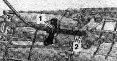
Turn away (if available) bolt "arrow", put the coolant circulation pump "V50" aside.
Using a release lever "80-200", detach the ball joint "2" of the selector cable from the gearbox lever. Remove the locking bracket "1" and release the selector cable.
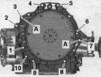
Unscrew the bolts "2...5" that connect the gearbox and engine and are accessible from above. "Pos. A" should not be taken into account.
Secure the right catalytic converter to prevent it from falling by loosely tightening the nut.
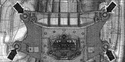
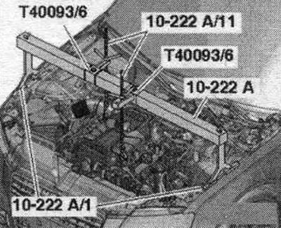
Cars with 3.0 l TFSI engine: Install the "10-222 A" crossmember with the "T40093/6" adapter on the left and right shock absorber strut cups, as shown in the figure. Attach the "10-222 A/11" lead screws to the front and rear engine mount eyes. Pre-tighten the motor slightly with the lead screws.
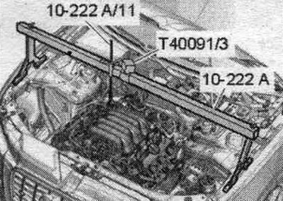
Cars with 3.2 l FSI engine: Install the "10-222 A" crossmember with the "T40091/3" connector on the shock absorber strut cups on the left and right, as shown in the figure. Attach the lead screw "10-222 A/11" to the right engine mounting eye.
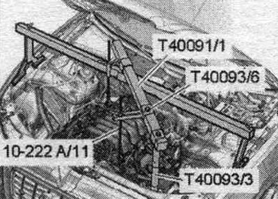
Install other parts of the "10-222 A" crossbar as shown in the figure. To do this, install the "T40093/3" support on the fold of the side member sheet. Attach the lead screw "10-222 A/11" to the left engine mounting eye. Pre-tighten the motor slightly with the lead screws.
Remove the subframe cross braces. If the powertrain support, steering gear or subframe crosspiece is incorrectly installed, the vehicle must not be placed on the wheels.
Cars with electric mechanical power steering: Disconnect plug "2" of the power steering control unit "J500" by loosening the "arrow" lock and pressing the release mechanism down. Disconnect connector "1" on the power steering control unit "J500". Release the wiring harness.
All
If present, unscrew the left and right "arrow" bolts and remove the heat shields "1".
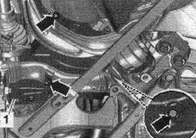
Unscrew the arrow bolts and remove the heat-insulating shield of the right drive shaft.
Unscrew the arrow bolts and remove the left drive shaft heat-insulating shield. Unscrew the left and right drive shafts from the shafts with the gearbox flange.
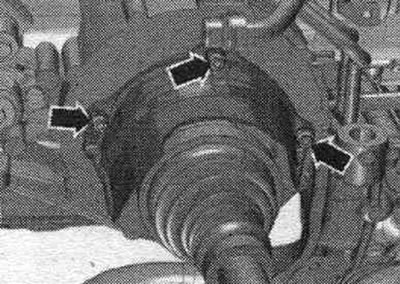
If present, unscrew the "arrow" bolts and remove the heat shield "1" of the propeller shaft.
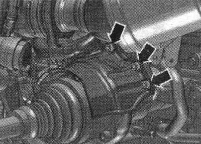
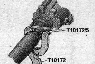
Car with a bolted driveshaft: Unscrew the bolts connecting the driveshaft to the gearbox, while holding it from turning using the counter support "T10172" with "T10172/5". Move the driveshaft towards the rear final drive; constant velocity joints are movable in the axial direction. Tie the cardan shaft to the side.
Vehicles with a plug-in cardan shaft: Use the vehicle data plate or the marking on the rear final drive to determine the type of rear final drive installed. Remove the propeller shaft.
All
Before working with electrical connectors, the specialist must "discharge electrostatic charge". Disconnect the gearbox plug connector by turning the rotary clamp counterclockwise "arrow".
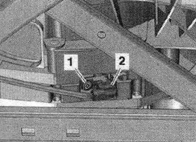
Disconnect connector "2" of engine speed sensor "G28" and release the gearbox wire. Ignore "Pos. 1".
Remove the intermediate steering shaft from the steering mechanism and slide it upward.
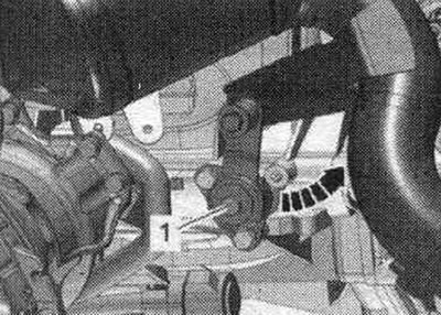
Unscrew bolt "1", press the locking tab away from the gearbox and tilt the "arrow" back.
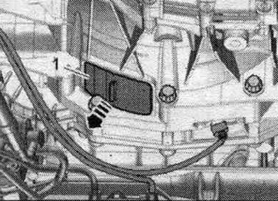
Remove cover "1" under the gearbox "arrow".
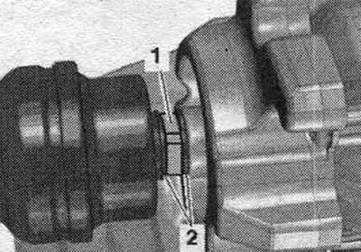
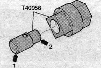
Insert the guide pin of the adapter "T40058" as follows: the large diameter "arrow 1" faces the engine, the small diameter
"arrow 2" is directed towards the adapter.
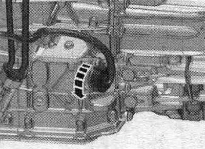
To loosen the flywheel bolts, hold the crankshaft from turning using the T40058 adapter and a bent ring spanner. During the final turn, rotate the crankshaft only in the direction of engine rotation "arrow". The illustration shows the work step on the 3.0 l TFSI engine.
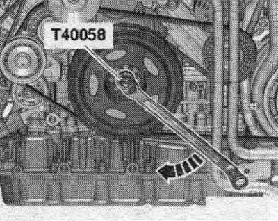
Unscrew the 6 flywheel "arrow" bolts; to do this, turn the crankshaft 60° in the direction of engine rotation.
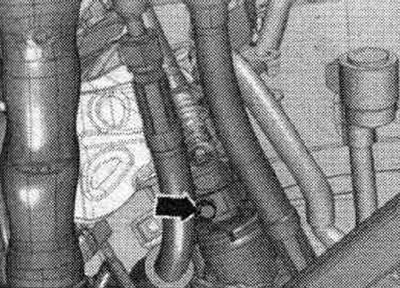
A/m with hydraulics. power steering: Place a device for filling and pumping out oil under the separation point. Unscrew the "arrow" bolts, disconnect the hydraulic line "1" from the steering gear and put it aside. Close open lines and pipes with clean plugs from the "VAS 6122" engine plug set.
All
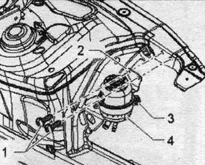
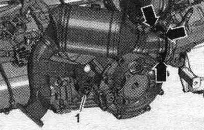
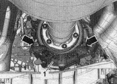
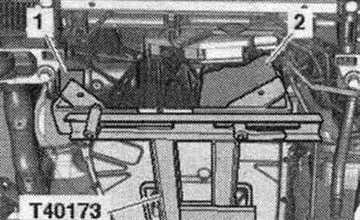
Unscrew bolt "1" of the starter. Remove the starter from the gearbox and leave it in the mounting position. position. Unscrew the remaining bolts "6...10" connecting the gearbox to the engine. Ignore "Pos. A". Do not touch the ATF pan with the T40173 transmission support. Install a powertrain lift with the prepared T40173 transmission mount under the transmission. At the front, the transmission mount must be installed as follows: on the left side, mounting block "2" fits into the flywheel hole in the transmission housing; on the right side of the gearbox, the gearbox mount is installed on the differential housing. To protect the housing, place rubber gasket "1" between the elements.
Secure the gearbox using tension belt "1". Unscrew the tunnel crossmember "arrow" bolts. Press the gearbox away from the engine and carefully lower it using a tilting tool.