
Table of contents: Cylinder head installation ↓ Compression check ↓
Cylinder head installation
Installation in reverse order.
Caution! Risk of damage to the sealing surface. Carefully remove any remaining sealant from the cylinder head and cylinder block. Avoid creating long scratches or burrs. Risk of damage to the cylinder block. There should be no oil or coolant in the blind holes of the cylinder head mounting bolts. Risk of a leaky cylinder head gasket. When repairing, carefully remove any remaining sealant from the cylinder head and cylinder block. Avoid creating long scratches or burrs. Carefully remove any remaining sandpaper and grinding material. The new cylinder head gasket should be removed from the packaging immediately before installation. To prevent damage to the silicone layer and the grooves of the cylinder head gasket, handle the gasket with particular care. Risk of damage to open valves. When installing a replacement cylinder head, remove the plastic base to protect the exposed valves only when it comes into direct contact with the cylinder head. There is a risk of damage to the valves and piston crowns after working on the valve train. To ensure that no valves are touching the cylinder head during operation, carefully rotate the engine at least 2 revolutions. Replace the bolts tightened to the specified torque. Replace self-locking nuts, lip seals, gaskets and seals. rings. Modification of cylinder heads of TDI engines is prohibited. Before installing the replacement cylinder head, it is necessary to lubricate the mating surfaces between the rocker arm and the working surface of the cams with oil. Hose fittings, air tubes and hoses must be cleaned of oil and grease before installation. To secure all hose connections, use clamps of the appropriate series. To ensure reliable fastening of the air duct hoses to the fittings, it is necessary to completely replace the coolant and oil after replacing the cylinder head or cylinder head gasket.
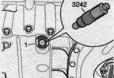
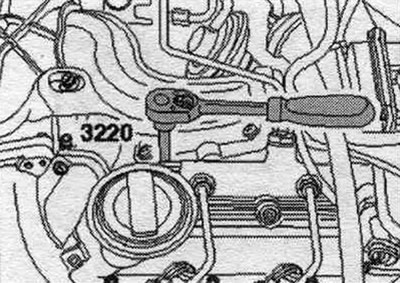
Before installing the cylinder head, set the crankshaft and camshafts to "TDC": Fixing bolt "3242" must be screwed in the "TDC" position of crankshaft "1".
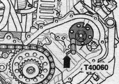
The camshafts on both cylinder heads must be locked with the "T40060" adjusting pin. The "arrow" pin in the "T40060" adjusting pin must be positioned parallel to the camshaft chain drive axis of symmetry.
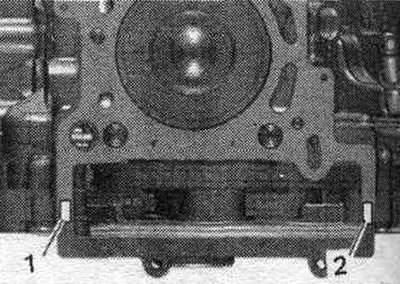
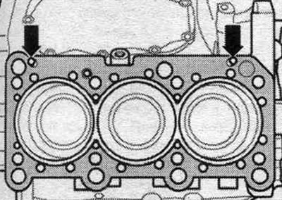
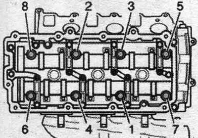
Pay attention to the markings on the cylinder head gasket:
1. Holes.
2. Part number.
Note: After replacing the cylinder head gasket or cylinder head, select a new cylinder head gasket according to the number of holes in the old gasket. If crankshaft components have been replaced, a new cylinder head gasket should be selected based on the piston protrusion at TDC. Left and right cylinder head gaskets cannot be confused; they have different shapes.
Clean the sealing surfaces from oil and grease. Observe the expiration date of the sealant. Cut off the tube tip along the front mark (opening diameter approx. 5 mm). The bolted connection of the parts must be closed 15 minutes after applying the sealant.
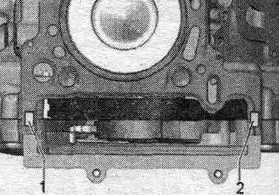
Left Cylinder Head: Apply beads of sealant "1" and "2" to the clean seating surface of the cylinder block and lower timing chain cover as shown in the figure.
The sealant is applied in the specified quantity.
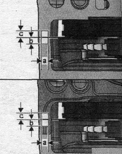
a = 7 mm, b = 7 mm, c = 7 mm.
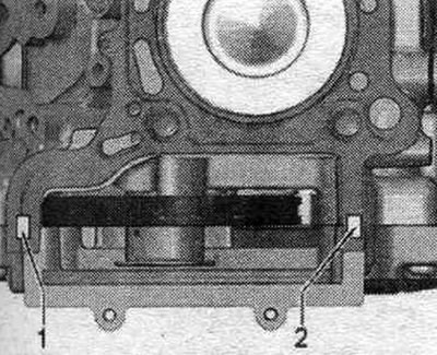
Install the cylinder head gasket. Apply sealant bead "1" and "2" to the cylinder head gasket as shown in the figure.
Right Cylinder Head: Apply beads of sealant "1" and "2" to the clean seating surface of the cylinder block and lower timing chain cover as shown in the figure.
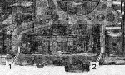
The sealant is applied in the specified quantity, a = 7 mm, b = 7 mm, c = 7 mm.
Install the cylinder head gasket. Apply bead of sealant "1" and "2" to the recesses of the cylinder head gasket.
All
Pay attention to the centering bushings "arrows" in the cylinder block. Cylinder head seal installation position: marked "up" or the cylinder head part number. Install the cylinder head.
Tighten the cylinder head bolts. After completing repairs, do not tighten the cylinder head bolts.
Left cylinder head: CAMA, CAMB, CCLA, CCWA, CCWB, CGKA, CGKB: timing belt tensioner roller and high-pressure pump timing belt. CAPA: Install the fuel injection pump toothed belt. Install the fuel injection pump connecting pipe. eGR. Install the dipstick guide tube.
Right cylinder head: Install the right upper coolant pipe. Install the right intermediate pipe
All
Install fuel. high-pressure lines. Installing the cylinder head cover. Install the upper part of the intake manifold. Install the camshaft drive chains. Change the oil. Replace coolant. Check fuel level. system for leaks.
Compression check
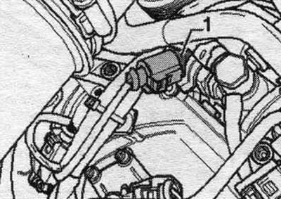
Oil temperature is approximately 80°C. Battery voltage is at least 12.5 V. Remove the engine cover. Disconnect all glow plug connectors. Disconnect the connector of the fuel pressure regulator valve "N276" "pos. 1" on the fuel rail of cylinder bank 1 (right). To relieve pressure in the fuel. turn on the engine briefly on the ramp.
Remove all glow plugs.
Install the "VAG1763/8" adapter instead of the glow plug and connect the "VAG 1763" compression tester to it.
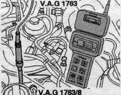
The second mechanic should crank the starter until the compression gauge stops showing an increase in pressure. Conduct a check of each cyl..
| Compression values | Bar of excess pressure |
| New | 28...33 |
| Maximum tolerance | 21 |
| Maximum difference between cylinders | 5 |
Installation
Installation in reverse order. Install glow plugs. Since the plug connectors were removed while the engine was running, the engine control unit stored the error: "Query fault memory" in the "Vehicle self-diagnosis" mode.