
Table of contents: Removal and installation camshafts -… ↓ Removal and installation camshafts -… ↓
Caution! Risk of damage to valves and piston crowns after working on the valve train. Since the hydraulic lifters must be settled, after installing the camshafts the engine should not be run for approx. 30 min. To ensure that no valves come into contact with the cylinder head during operation, carefully crank the engine at least 2 revolutions.
The figure shows the cylinder head of cylinder bank 2 (left).
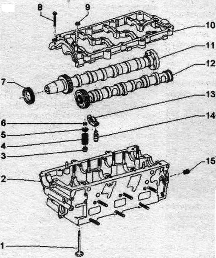
1. Valve: cannot be machined, only lapping is allowed; mark mont. reinstallation position.
2. Cylinder head: treat valve seats.
3. Oil seal: replace with cylinder head installed.
4. Valve spring.
5. Valve spring plate.
6. Valve cracker.
7. Camshaft seal.
8. Bolt.
9. Nut.
10. Camshaft frame: with integrated camshaft bearings.
11. Intake camshaft: maximum runout: 0.01 mm.
12. Exhaust camshaft: maximum runout: 0.01 mm.
13. Rocker arm: mark installation. reinstallation position; check the roller bearing for ease of movement; before installation, lubricate the working surfaces.
14. Hydraulic compensator: mark installation. reinstallation position; before installation, lubricate the working surfaces.
15. Pressure limiting valve 1.0 bar: for lubrication points in the cylinder head; in the latest designs it is absent; 25 Nm.
Crankshaft bearing frame on the left cylinder head
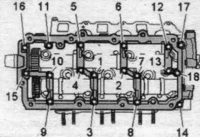
Tighten the bolts and nuts in 2 stages in the specified order.
| Step | Bolts/nuts | Tightening torque |
| 1 | "1...18" | Screw it in manually until it stops. The frame must fit snugly against the cylinder head over the entire mating surface |
| 2 | "1...18" | 9 Nm |
Crankshaft bearing frame on the right cylinder head
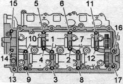
Tighten the bolts and nuts in 2 stages in the specified order:
| Step | Bolts/nuts | Tightening torque |
| 1 | "1...17" | Screw it in manually until it stops. The frame must fit snugly against the cylinder head over the entire mating surface |
| 2 | "1...17" | 9 Nm |
Removal and installation camshafts - left cylinder head
Remove the left timing chain from the camshaft. Remove the upper part of the intake manifold.
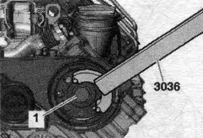
Remove the fuel injection pump timing belt. Loosen bolt "1" of the timing belt drive pulley by approximately 2 turns, using counterstop "3036" for this.
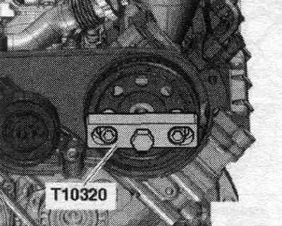
Remove the timing belt drive pulley using the T10320 puller. Remove the left cylinder head cover.
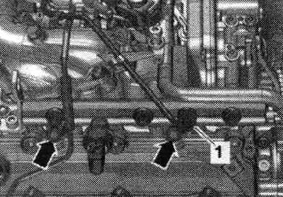
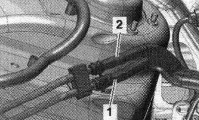
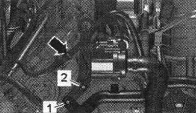
Unscrew the union nut "1" of the high-pressure line. Unscrew the arrow bolts and remove the fuel tank. ramp with the left cylinder head.
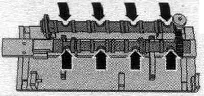
Loosen the crankshaft frame bolts and nuts in sequence. "18...1". When removing the camshafts, pay attention to the rocker arms and compensators. Carefully remove the crankshaft frame from the camshafts.
Install
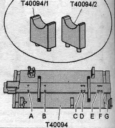
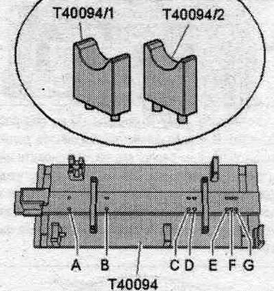
Replace the right cylinder head front cover. Risk of damage to the thrust bearing in the crankshaft frame. Install camshafts strictly in accordance with the description using the camshaft installation tool "T40094". Risk of contamination of the system. lubricants. Seal the exposed cylinder head parts. Remove any remaining sealant from the cylinder head and crankshaft frame, for example, using a rotating brush attachment with plastic bristles. Clean the seating surfaces; there should be no oil or grease on them. Lubricate the working surfaces of the camshafts with oil. Equip the camshaft installation tool "T40094" as follows: insert the support "T40094/2" into the socket "A", insert the support "T40094/1" into the socket "D".
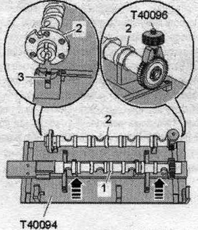
Install the exhaust camshaft "1" on the support "T40094/1" and "T40094/2". Turn the exhaust camshaft so that it can be locked with the retainer in the "TDC" position "arrow". Install the camshaft tool "T40096" on the exhaust camshaft teeth so that each jaw of the clamping device engages in the corresponding half of the toothed gear. Clamp the clamping fixture with the knurled wheel until the tooth profiles are flush with each other.
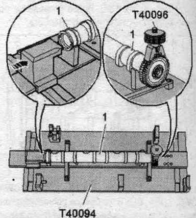
Install intake camshaft "2" into camshaft installation tool "T40094". Locking pin "3" must fit into the groove of the intake camshaft. Move the exhaust camshaft "1" towards the intake camshaft "arrows" so that the teeth engage.
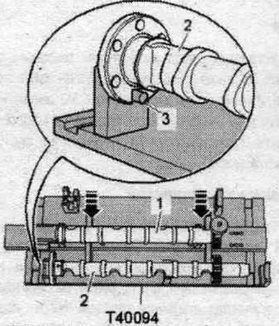
Check the correct position of the camshaft: the "arrow" recesses in both camshafts must be directed outward.
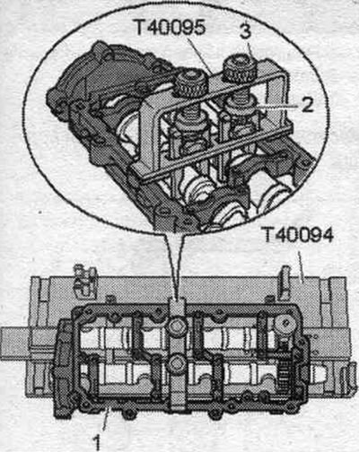
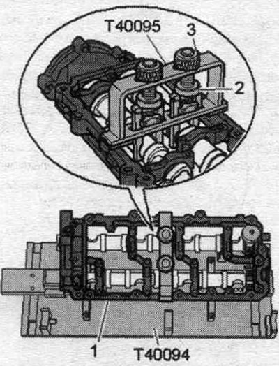
Install crankshaft frame "1" on both camshafts. All camshaft bearings must be located on the camshafts. Install the "T40095" camshaft tool onto the camshafts. To do this, align the gripping pliers and clamp them using knurled nuts "2." Pull the camshaft upward by tightening knurled nuts "3.".
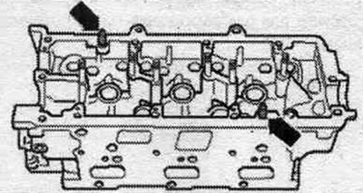
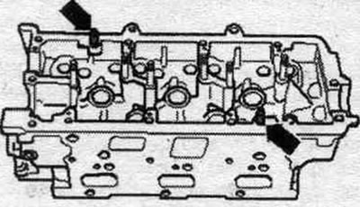
Check whether the centering pins "arrows" are installed in the cylinder head. If the centering pins are missing, insert them.
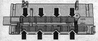
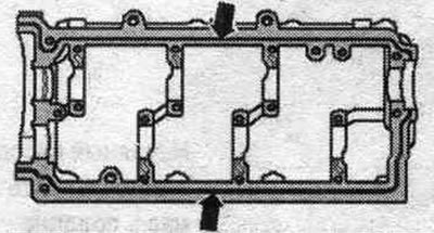
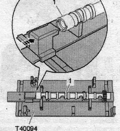
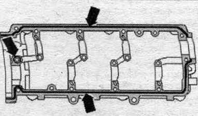
Observe the expiration date of the sealant. Cut off the tube tip along the front mark (opening diameter approx. 1.5 mm). For better presentation, the crankshaft frame is shown without camshafts. Turn the crankshaft frame over. Danger of blockage of system channels. lubrication when there is excess sealant. The sealant beads must not be thicker than the prescribed size. Apply a bead of "arrow" sealant to the clean camshaft frame mounting surfaces as shown in the figure. The grooves of the seating surface must be filled with sealant. The sealant beads should protrude 1.5–2.0 mm above the mounting surface. Install the camshaft frame within 5 minutes of applying the sealant.
Check that all roller rocker arms are properly installed on the valve stem ends and compensators. Install the crankshaft frame with both camshafts and the "T40095" camshaft installation tool onto the cylinder head. Tighten the crankshaft frame bolts. Remove the camshaft installation tool "T40095" and "T40096." After installing the crankshaft frame, allow the sealant to cure for approximately 30 minutes. Reinstall in reverse order. Install the left cylinder head cover. Replace the camshaft oil seal. Install the fuel injection pump timing belt. Install the upper part of the intake manifold. Install the camshaft chain.
Removal and installation camshafts - right cylinder head
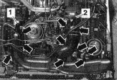
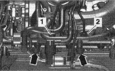
Remove the right chain from the camshaft. Remove the right cylinder head cover. Disconnect the supply "1" and return "2" fuel lines.
Unscrew the union nuts "1" and "2". Unscrew the bolts "arrows" and put aside the fuel. ramp with connected fuel. hoses.
Release the "arrow" wiring harness using the "80-200" lever. Ignore "Pos. 1, 2".
Loosen the crankshaft frame bolts and nuts in sequence. "17...1". When removing the camshafts, pay attention to the rocker arms and compensators. Carefully remove the crankshaft frame from the camshafts.
Install
Risk of damage to the thrust bearing in the crankshaft frame. Install camshafts strictly in accordance with the description using the camshaft installation tool "T40094". Risk of contamination of the system. lubricants.
Seal the exposed cylinder head components. Remove any remaining sealant from the cylinder head and crankshaft frame, for example, using a rotating brush with a plastic bristle attachment. Clean the seating surfaces; there should be no oil or grease on them. Lubricate the working surfaces of the camshafts with oil. Equip the camshaft installation tool "T40094" as follows: insert the support "T40094/2" into the socket "B", insert the support "T40094/1" into the socket "C".
Install the exhaust camshaft "1" on the support "T40094/1" and "T40094/2". Turn the exhaust camshaft so that it can be locked with the locking pin in the "TDC" position "arrow".
Install intake camshaft "2" into camshaft installation tool "T40094". Locking bridge "3" should fit into the groove of the intake camshaft. Install the T40096 camshaft tool onto the intake camshaft teeth so that each arm of the clamp fits into the corresponding half of the timing gear. Clamp the clamping fixture with the knurled wheel until the tooth profiles are flush with each other. Move the exhaust camshaft "1" towards the intake camshaft "arrows" so that the teeth engage.
Check the correct position of the camshaft: the "arrow" recesses in both camshafts must be directed outward.
Install crankshaft frame "1" on both camshafts. All camshaft bearings must be located on the camshafts. Install the "T40095" camshaft tool onto the camshafts. To do this, align the gripping pliers and clamp them using knurled nuts "2." Pull the camshaft upward by tightening knurled nuts "3.".
Check whether the centering pins "arrows" are installed in the cylinder head. If the centering pins are missing, insert them.
Cut off the tube tip along the front mark (opening diameter approx. 1.5 mm). For better presentation, the crankshaft frame is shown without camshafts. Turn the crankshaft frame over. Danger of blockage of system channels. lubrication when there is excess sealant. The sealant beads must not be thicker than the prescribed size. Apply a bead of "arrow" sealant to the clean camshaft frame mounting surfaces as shown in the figure. The grooves of the seating surface must be filled with sealant. The sealant beads should protrude 1.5–2.0 mm above the mounting surface. Install the camshaft frame within 5 minutes of applying the sealant.
Check that all roller rocker arms are properly installed on the valve stem ends and compensators. Install the crankshaft frame with both camshafts and the "T40095" camshaft installation tool onto the cylinder head. Tighten the crankshaft frame bolts. Remove the camshaft installation tool "T40095" and "T40096." After installing the crankshaft frame, allow the sealant to cure for approximately 30 minutes. Reinstall in reverse order. Install the right cylinder head cover. Press the new sealing cover flush with a suitable mandrel. Install the camshaft chain.
(Text provided by the online resource: audimanual)