
Table of contents: Hose connection diagram ↓ Draining and filling the coolant ↓
CAUTION! Risk of burns from hot steam and hot coolant. When the engine is warm, the cooling system is under excess pressure. To relieve excess pressure, place the expansion cap over the expansion tank. coolant reservoir with a rag and carefully open it. To secure all hose connections, use clamps of the appropriate series. Arrows applied to the ends of the tubes and hoses of the system. cooling, must be located opposite each other.
Hose connection diagram
Cars without independent heater
The arrows show the direction of coolant flow.
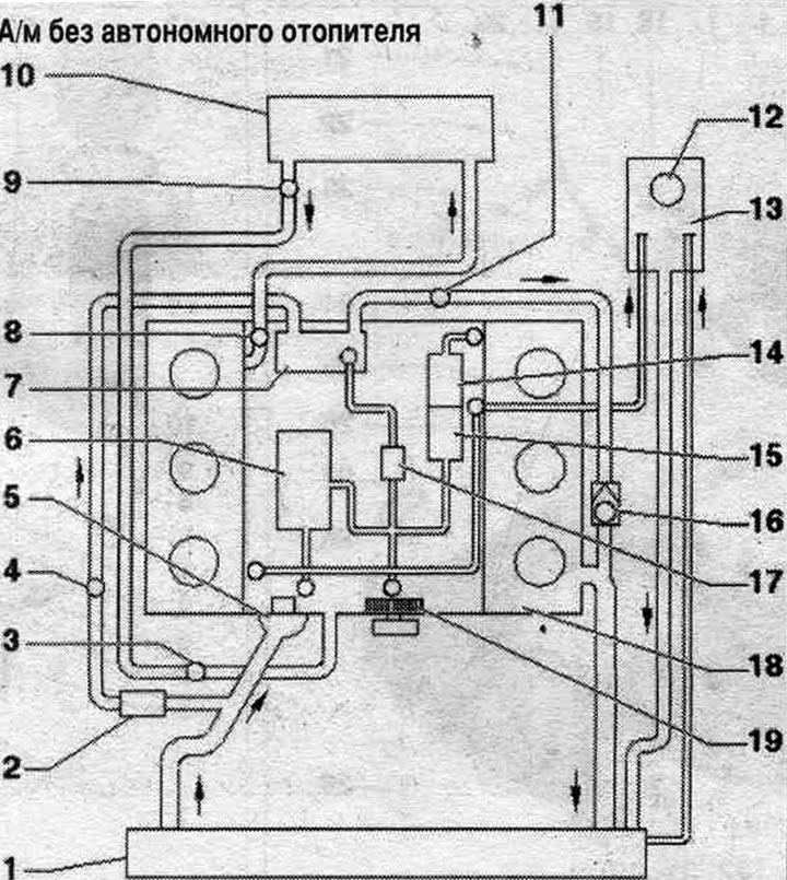
1. Radiator: after replacement, change the coolant.
2. Radiator pump system. exhaust gas recirculation "V400".
3. Air bleed screw.
4. Radiator outlet coolant temperature sensor "G83".
5. Thermostat.
6. Oil cooler: after replacement, change the coolant.
7. Radiator system. eGR: Change the coolant after replacement.
8. Coolant temperature sensor "G62".
9. Ventilation hole.
10. Heater heat exchanger: after replacement, change the coolant.
11. Air bleed screw.
12. Expansion cover. coolant reservoir.
13. Expansion tank.
14. Switching valve system. exhaust gas recirculation.
15. Servo motor system. eGR "V338": with system potentiometer. exhaust gas recirculation "G212".
16. Check valve: the arrow shows the direction of flow.
17. Thermostat system. exhaust gas recirculation.
18. Cylinder head to cylinder block: after replacement, change the coolant.
19. Water pump.
Car with independent heater
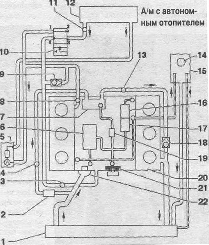
1. Radiator: after replacement, change the coolant.
2. Radiator pump system. exhaust gas recirculation "V400".
3. Air bleed screw.
4. Radiator outlet coolant temperature sensor "G83".
5. Autonomous heater: with circulation pump "V55".
6. Oil cooler: after replacement, change the coolant.
7. Radiator system. eGR: Change the coolant after replacement.
8. Coolant temperature sensor "G62".
9. Check valve.
10. Heater coolant shut-off valve "N279".
11. Ventilation hole.
12. Heater heat exchanger: after replacement, change the coolant.
13. Air bleed screw.
14. Expansion cover. coolant reservoir.
15. Expansion tank.
16. Switching valve system. exhaust gas recirculation.
17. Servo motor system. eGR "V338": with system potentiometer. exhaust gas recirculation "G212".
18. Check valve.
19. Thermostat system. exhaust gas recirculation.
20. Cylinder head to cylinder block: after replacement, change the coolant.
21. Water pump.
22. Thermostat.
Draining and filling the coolant
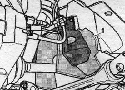
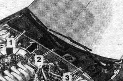
Open the expansion lid. tank. Remove noise insulation shields "1" and "2". Install a tray for service cranes under the engine. Unscrew the "arrow" plug of the connecting pipe and drain the coolant.
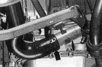
Remove the coolant hose from the left lower pipe of the system. cooling, loosen the hose clamp "arrow", and drain the coolant.
Remove cover "1" of the propeller shaft in the wheel arch on the right.
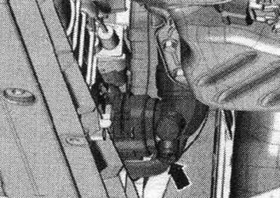
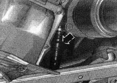
Cars with a nipple connector for the lower right coolant hose: remove the coolant hose "arrow" by pressing the clamp, and drain the coolant.
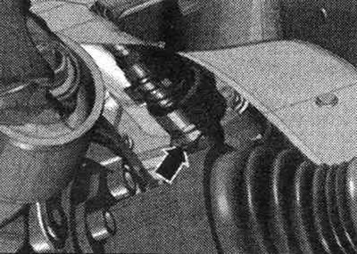
Cars with a nipple connector on the side member: Disconnect the coolant hose by pressing the clamp "arrow" and drain the coolant.
Bay
The ignition is off.
Note: The cooling system is filled with a coolant solution and coolant additives for the entire year. Only coolant specified in the Electronic Parts Catalog should be used. Other concentrates may worsen the properties of the coolant, especially its anti-corrosion properties. The resulting damage may cause leaks in the system. cooling and lead to serious engine malfunctions. A coolant with the correct ratio of mixture components prevents the formation of corrosion and limescale. In addition, they increase the boiling point. Therefore, throughout the year in the system. concentrate must be present for cooling. Especially in countries with tropical climates and high engine loads, coolants with a high boiling point reliably protect the engine during operation. The freezing point of the coolant must be at least -25°C, and at least -35°C in countries with an arctic climate. It is also prohibited to reduce the proportion of concentrate in the coolant during the warm season or when operating in countries with a warm climate by adding it to the system. cooling water. The concentrate content should be at least 40%. If climatic conditions require the use of a coolant with a lower freezing point, the coolant additive content can be increased to 60% (coolant freezing point is -40°C). A different proportion will reduce the freezing point of the coolant. in addition, the cooling effect is reduced. Use only clean drinking water to mix coolant. When replacing a radiator, heater heat exchanger, cylinder head, cylinder head gasket or cylinder block, reusing drained coolant is prohibited. To check the freezing point of the coolant, use a T10007 refractometer. Use clamps of the appropriate series to secure all hose connections.
Ratio of components in coolant
- Additive (40%) and water (60%) to ensure freezing temperature of -25°C
- Additive (50%) and water (50%) to ensure freezing temperature of -35°C
- Additive (60%) and water (40%) to ensure freezing temperature of -40°C
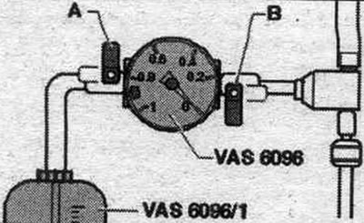
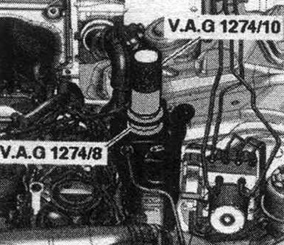
Cars with a nipple connector for the lower right coolant pipe: connect the system hose. cooling. Vehicles with a nipple connector on the side member: connect the system hose. cooling. Connect the coolant hose to the left pipe "arrow". Screw in the drain plug "arrow" with a new seal. ring into the connecting nipple. Pour into the tank of the device for filling the system. cooling "VAS 6096" at least 12 liters of pre-mixed coolant in the correct proportion: Screw on the adapter of the system tester. cooling "VAG 1274/8" to the expansion tank. Install the device for filling the system. cooling "VAS 6096" on the adapter "VAG 1274/8". Place the drain hose "1" into a small container "2".
The exhaust air carries a small amount of coolant, which must be collected. Close taps "A" and "B" by turning them perpendicular to the direction of flow. Connect hose "3" to the compressed air line. Pressure: 6...10 bar excess pressure.
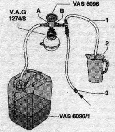
Open valve "B" by turning it in the direction of flow. A vacuum is created in the cooling system using an ejector pump; the indicator arrow should be in the green field. Open tap "A" briefly, turning it parallel to the direction of flow so that the hose of the tank of the device for filling the system. the "VAS 6096" cooling system is full of coolant. Close valve "A" again. Open valve "B" for 2 minutes. A vacuum continues to be created in the cooling system using the ejector pump; the indicator arrow should be in the green field. Close valve "B". The indicator arrow should remain in the green field, in which case there is a vacuum in the system. cooling will be enough for its subsequent filling. If the arrow is below the green field, then you should repeat the previous operations. When the vacuum decreases, check the system. cooling for leaks. Remove the compressed air hose. Open tap "A".
Due to the vacuum, the fluid coming out of the tank of the device for filling the system. cooling "VAS 6096" Coolant fills the system.. Remove the device for filling the system. cooling "VAS 6096" with adapter "VAG 1274/8" on expansion. tank. Attach the tube "VAG 1274/10" on the adapter "VAG 1274/8". Fill with coolant until the system tester tube reaches the level. the cooling system was completely filled. If necessary, add more during the air removal process.
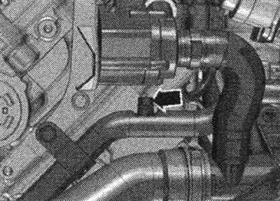
Remove the engine cover "arrows". Open the bleed screw "arrow" of the coolant tube while the coolant is draining. Close the bleed nipple.
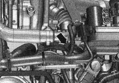
Open the air bleed screw "arrow" of the rear coolant pipe until the coolant drains. Close the bleed nipple.
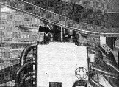
Remove the middle element "2" or the entire cover of the water drainage box (depending on the design).
Loosen and remove the system hose. cooling system going to the heat exchanger so that the coolant comes out of the "arrow" vent in the cooling system hose.
Place the coolant hose onto the connecting nipple and secure it. On a vehicle with independent heating, turn on the heater for approx. for 30 seconds. Tighten the expansion cap. tank until it clicks. Start the engine. Set the temperature for all zones to "HI" and, if possible, set the ventilation level to the lowest level (0). Turn off the air conditioner compressor by pressing the AC button. The tester LED in the button should not be lit. The engine should run at 2000 rpm for 3 minutes. Leave the engine to idle. drive until the 2 large coolant hoses on the radiator are warm. The engine should run at 2000 rpm for 2 minutes. Turn it off and let the engine cool. Install noise insulation screens. Check the coolant level. When the engine is cold, the coolant level should be at the -MAX- mark. If the engine is warmed up to operating temperature, the coolant level may be above the -MAX- mark.
This publication is borrowed from the resource: AUDImanual