
Table of contents: Radiator and radiator fan ↓ Removal and installation the… ↓
Radiator and radiator fan
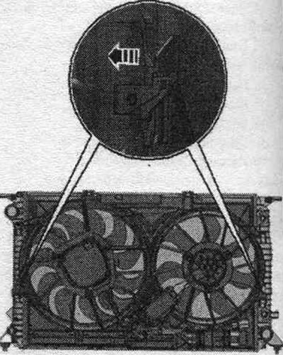
The figure shows the components of the 1000W fan control unit.
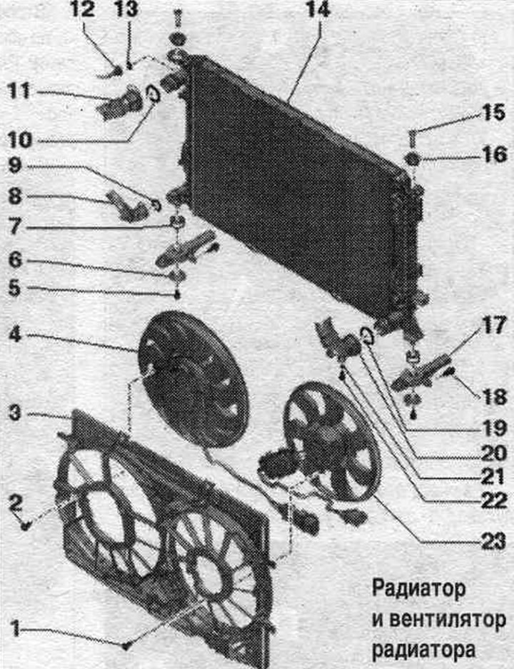
1/2. Bolt: 5 Nm.
3. Fan frame.
4. Radiator fan "V7": depending on the configuration with a separate fan control unit "J293".
5. Bolt: 3.5 Nm.
6. Lining.
7. Rubber support: for radiator.
8. Cooling system hose: to remove, loosen the clamp; connect to the radiator.
9/10. O-ring: replace.
11. Cooling system hose: to remove, loosen the clamp; connect to the radiator.
12. Cooling system hose: to the expansion tank.
13. Sealing ring: replace.
14. Radiator: after replacement, drain the old coolant and fill it with new coolant.
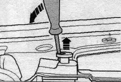
15. Lock bolt: Unlock with a screwdriver and remove.
16. Rubber buffer.
17. Radiator console.
18. Bolt.
19. Sealing ring: replace.
20. Cooling system hose: to remove, loosen the clamp; connect to the radiator.
21. Sealing ring: replace.
22. Drain plug.
23. Radiator fan 2 "V177": except for the 400W fan control unit; depending on the configuration with an integrated fan control unit "J293".
Radiator Fan Control Unit - Tightening Torque
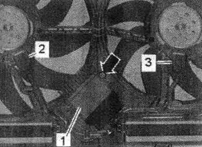
Tighten the arrow bolt to 4.5 Nm.
Removal and installation the radiator together with the fan frame
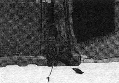
The radiator and fan frame can only be removed and installed as an assembly. Remove the front noise insulation "1". Remove the front and rear noise insulation shield. Remove the intercooler. Remove the right headlight.
On vehicles with headlight washers, remove the right headlight washer nozzle.
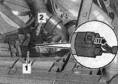
Disconnect the plug connector "1" of the impact sensor.
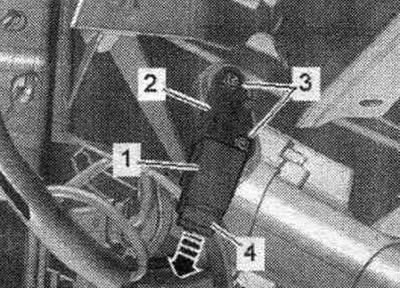
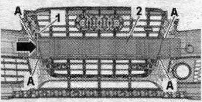
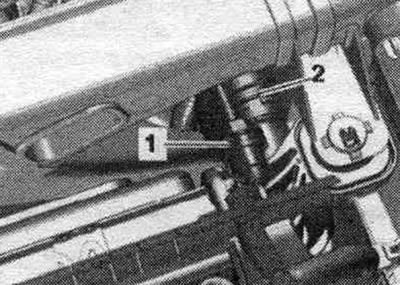
Loosen bolts "1" and "2". Disconnect and remove the right headlight bracket "arrow". Ignore "Pos. 3".
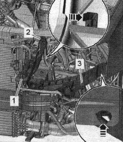
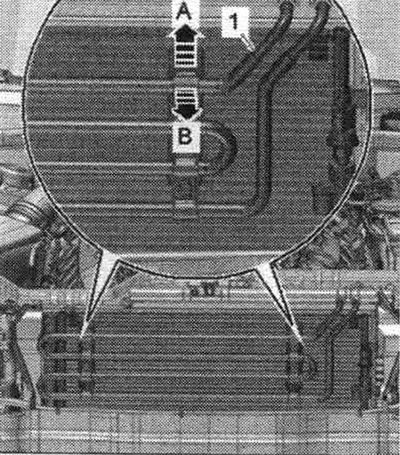
Place a service tray under the engine. Unscrew the "arrow" plug on the connecting pipe and drain the coolant. Then remove the connecting pipe from the radiator by loosening the retaining clip.
Remove the connecting nipple from the radiator by loosening the "arrow" clamp.
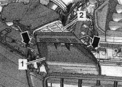
Disconnect the plug connectors "1" and "2" of the radiator fan by moving the latch back "arrow" and pressing on the locking tabs.
A/m with multitronic O A W/CP with dual clutch 0B5/AKP 0B6
Place a device for pumping and collecting oil under the disconnection point. Loosen the arrow bolts and disconnect the ATF lines from the radiator. To prevent ATF oil leakage, tie the ATF lines to the side member.
Close open lines and pipes with clean plugs from the VAS 6122 engine plug kit.
All
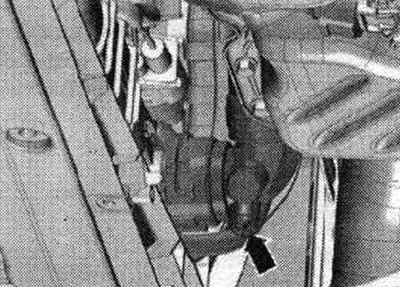
Remove the connecting nipple from the radiator by loosening clamps "1" and "2".
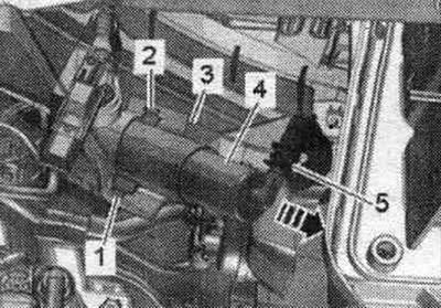
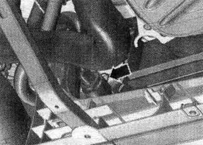
Unscrew the "arrow" bolts. Remove the air duct "1" from the intermediate flange "2" of the air duct housing. filter.
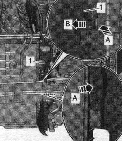
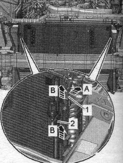
If present, unlock the retaining clips "arrow A" and tilt the power steering coolant hoses "1" forward "arrow B". Remove the power steering hoses from the condenser upwards and place them on the engine.
Release the clamps "arrow A" and remove the air duct "1" on the left and right "arrow B".
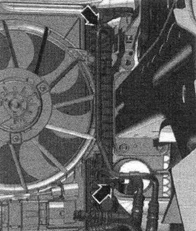
Release the radiator retainers on the left and right and remove them upwards "arrows".
Unscrew the bolts "1" on the left and right and remove the console and radiator from the radiator frame "arrow". Lower the radiator slightly.
The second mechanic should release the clamps "1" in the direction of "arrow A" and remove the condenser "2" upward from the radiator mounts "arrow B". Tilt the condenser forward with the hoses connected. Remove the radiator.
Press the locking tabs of the fan frame on the left and right "arrow" simultaneously and remove the fan frame from the radiator in an upward direction.
Install
Installation in reverse order. Install the air duct of the intermediate flange of the air housing. filter. Cars with multitronic 0AW/dual clutch transmission 0B5/automatic transmission 0B6: screw on the ATF lines. Install the right system injector. headlight cleaning. Install the right headlight. Install the intercooler. Install the fender liner and front sound insulation. Connect the coolant hose to the nipple connector. Fill with coolant. If the radiator was replaced, change the coolant.