
Installation locations (CAMA, CAMB, CCWA, CCWB, CGKA, CGKB)
Right side of the motorcycle. compartment
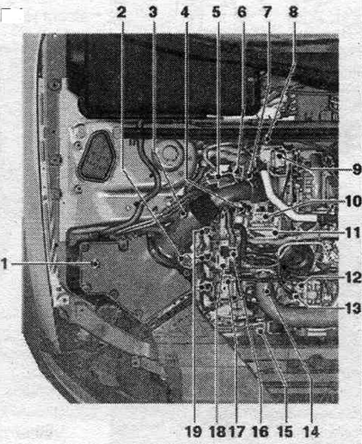
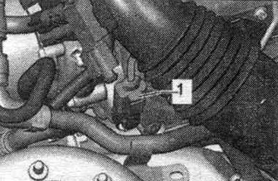
1. Air bypass valve. filter "N275": units (bypass damper with air bypass damper valve. filter "N275") are not installed in all equipment variants and not for all countries; if a bypass damper is installed, it is located in the air duct housing. filter, and air bypass valve. the "N275" filter is attached to the outside of the air intake housing. filter.
2. Air flow meter "G70".
3. Hall sensor "G40" (camshaft position sensor).
4. Fuel pressure regulating valve "N276": After replacing the high-pressure pump or the fuel pressure regulating valve "N276", it is necessary to carry out re-adaptation.
5. Exhaust gas pressure sensor 1 "G450": after replacement, adjustment must be made.
6. Plug connector: exhaust gas temperature sensor 4 "G648" (CAMA, CAMB, CCWA, CCWB, CGKA, CGKB), exhaust gas temperature sensor 3 cylinder bank 1 "G496" (CAPA).
7. Coolant temperature sensor "G62".
8. Exhaust gas temperature sensor 4 "G648" (CAMA, CAMB, CCWA, CCWB, CGKA, CGKB): exhaust gas temperature sensor 3 cylinder bank 1 "G496" (CAPA).
9. Turbocharger control unit 1 "J724".
10. Electrical connector of the exhaust gas temperature sensor 1 "G235": installed only on vehicles with engine letter designations CAPA, CCWA, CCWB; exhaust gas temperature sensor 1 "G235".
11. Intake manifold flap motor "V157": cylinder bank 1; intake manifold.
12. Connecting the return fuel. highways.
13. Fuel connection. highways.
14. Oil pressure sensor: oil pressure sensor "F1" on engines with the letter designation CAPA, CAMA, CAMB; oil pressure sensor for low pressure "F378" on engines with the letter designation CCWA, CCWB, CGKA, CGKB.
15. Radiator pump system. exhaust gas recirculation "V400".
16. Fuel temperature sensor "G81".
17. Radiator outlet coolant temperature sensor "G83".
18. Pressure reducing valve: in the drainage pipes of the 1st and 2nd rows of cylinders; the function of the pressure reducing valve is to ensure residual pressure in the return fuel. highways (scope of control) approx. 10 bar, which is necessary for piezo injectors to operate normally; the pressure reducing valve should only be replaced as a set with the return fuel. highways; after replacement, it is necessary to let the engine run at idle. run for about 2 minutes to remove air from the fuel. syst.
19. Injection modules (piezo injectors): cylinder bank 1.
Left side of the motorcycle. compartment
Nodes A through J are not shown in the drawing.

1. Plug connector: exhaust gas temperature sensor 3 "G495" (CAMA, CAMB, CCWA, CCWB, CGKA, CGKB), exhaust gas temperature sensor 2 "G448" (CAPA).
2. Exhaust gas temperature sensor 3 "G495" (CAMA, CAMB, CCWA, CCWB, CGKA, CGKB): exhaust gas temperature sensor 2 "G448" (CAPA); installed behind the catalytic converter; 45 Nm.
3. Lambda probe "G39" with lambda probe heating element "Z19": 50 Nm.
4. Intake manifold flap motor 2 "V275": cylinder bank 2; intake manifold.
5. Plug connector of the lambda probe "G39".
6. Engine control unit "J623".
7. Boost pressure sensor -G31-: with intake air temperature sensor "G42".
8. Throttle control unit "J338": 9 Nm.
9. Fuel pressure sensor "G247".
10. Injection modules (piezo injectors): cylinder bank 2.
11. Radiator changeover valve system. exhaust gas recirculation "N345".
12. Servo motor system. exhaust gas recirculation "V338".
13. Fuel injection pump: with fuel metering valve "N290"; on vehicles with CAMA, CAMB, CCWA, CCWB, CGKA, CGKB engines, after replacing the fuel injection pump, the first refueling should be performed (to prevent dry running); after replacing the high-pressure pump or the fuel pressure regulating valve "N276", it is necessary to carry out re-adaptation.
14. Fuel metering valve "N290": do not open; installed directly into the fuel injection pump.
15. System temperature sensor. exhaust gas recirculation "G98".
16. Temperature sensor connector in the system. exhaust gas recirculation "G98".
17. Vacuum tank: for switching valve system. exhaust gas recirculation.
A. Relay and fuse block in the switchboard. block in the left water drainage box.
B. Low-power heating relay "J359" and high-power heating relay "J360".
C. Brake light switch "F" and brake pedal switch "F47": in the footwell on the brake pedal.
D. Accelerator pedal position sensor "G79" and accelerator pedal position sensor 2 "G185".
E. Exhaust gas temperature sensor 1 "G235": installed only on CAPA, CCWA, CCWB vehicles; on a turbocharger; 45 Nm.
F. Engine speed sensor "G28".
G. Additional fuel pump "V393": installed only on engines: CAMA, CAMB, CCWA, CCWB, CGKA, CGKB.
H. Oil pressure sensor "F22": installed only on engines: CCWA, CCWB, CGKA, CGKB.
I. Oil pressure regulating valve "N428": installed only on engines: CCWA, CCWB, CGKA, CGKB.
J. Diesel particulate filter: mounted on the bottom; one-piece unit with catalyst; after replacement, adjustments must be made.
After replacing the exhaust gas pressure sensor 1 "G450" and/or the dust filter, it is necessary to carry out adaptation, which will reset the values. The procedure is described in Guided Fault Finding or Guided Functions and requires the use of a diagnostic tester.
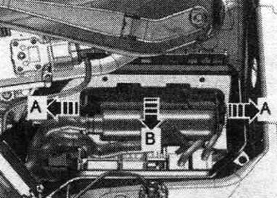
Installation location of the engine control unit "J623"
On the left there is a switch. block in motorcycle. compartment.
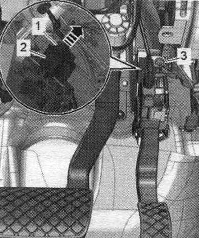
Accelerator pedal position sensor "G79" and accelerator pedal position sensor 2 "G185"
The accelerator pedal position sensor "G79" and the accelerator pedal position sensor 2 "G185" are integrated into the accelerator pedal module and cannot be replaced separately.
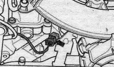
Fuel pressure sensor "G247" "1" on cylinder bank 2
Hall sensor "G40" "1" on cylinder bank 1
Details of the right cylinder bank
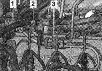
1. Fuel pressure regulating valve "N276". 2. Fuel temperature sensor "G81". 3. Pressure reducing valve in the fuel return. highways.
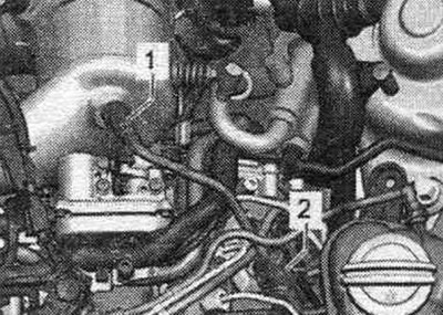
Installation locations
1. Electrical connector of the temperature sensor in the system. eGR "G98". 2. EGR servomotor. eGR valve "V338". 3. Radiator changeover valve system. eGR "N345". 4. System temperature sensor. exhaust gas recirculation "G98".
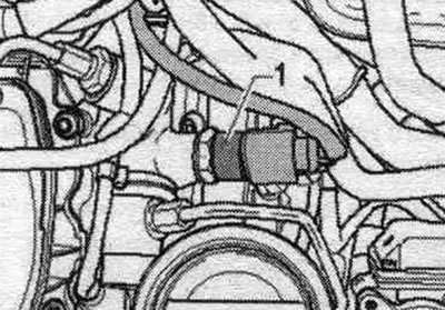
Radiator pump system. exhaust gas recirculation "V400" "1"
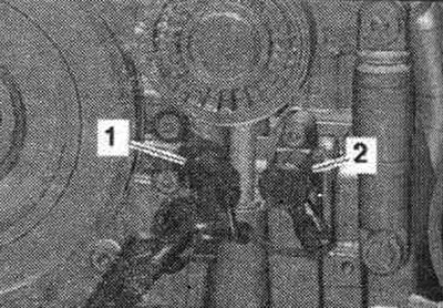
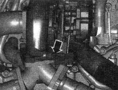
Oil pressure sensor "F1" "arrow" (CAPA, CAMA, CAMB)
Low pressure oil pressure sensor "F378" "1" (CCWA, CCWB, CGKA, CGKB)

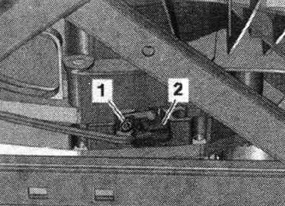
Oil pressure regulation (CCWA, CCWB, CGKA, CGKB)
1. Oil pressure sensor "F22". 2. Oil pressure regulating valve "N428".
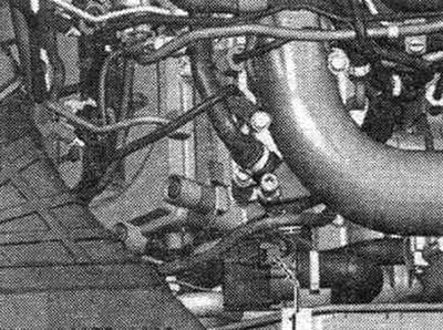
Boost pressure sensor "G31" with intake air temperature sensor "G42" "arrow"
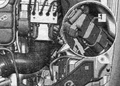
Installation location of the lambda probe "G39"
1. Lambda probe "G39". 2. Plug connector of the lambda probe "G39".
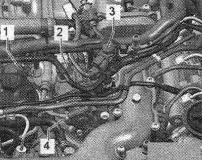
Installation locations
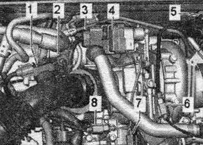
1. Exhaust gas pressure sensor 1 "G450". 2. Electrical connector of exhaust gas temperature sensor 3, bank 1 "G496" (CAPA). 2. Electrical connector of exhaust gas temperature sensor 4 "G648" (CAMA, CAMB. CCWA, CCWB, CGKA, CGKB). 3. Electrical connector turbocharger control unit 1 "J724". 4. Turbocharger control unit 1 "J724". 5. Exhaust gas temperature sensor 2 "G448" (CAPA). 5. Exhaust gas temperature sensor 3 "G495" (CAMA, CAMB, CCWA, CCWB, CGKA, CGKB). 6. Electrical connector of exhaust gas temperature sensor 2 "G448" (CAPA). 6. Electrical connector of exhaust gas temperature sensor 3 "G495" (CAMA, CAMB, CCWA. CCWB, CGKA. CGKB). 7. Intake manifold flap motor "V157". 8. Electrical connector for exhaust gas temperature sensor 1 "G235" (only 3.0L CAPA, CCWA, CCWB engines).
Exhaust gas temperature sensor 1 "G235" "arrow" (only 3.0L CAPA, CCWA, CCWB engines)
Engine speed sensor "G28" "2"
Add. fuel pump "V393" "3" (CAMA, CAMB, CCWA, CCWB, CGKA, CGKB)
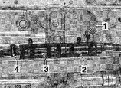
1. Additional plug connector. fuel pump "V393". 2. Fuel filter. 3. Additional fuel pump "V393". 4. Heating valve.
This article was copied from the website: Audimanual.ru