
Fuel system (CAPA)
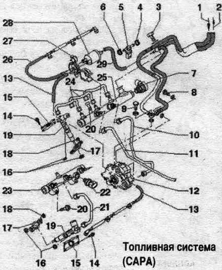
1. Fuel supply. main line: coming from fuel. filter.
2. Reverse fuel. main line: to the fuel tank; reverse fuel. the main line must not be kinked, damaged or clogged.
3. Hollow screw of return fuel. pipeline.
4. Clamp clamp.
5. Fuel temperature sensor "G81".
6. Clamp clamp.
7. Fuel pressure regulating valve "N276": installed on cylinder bank 1; do not reuse.
8. Hollow screw of return fuel. pipeline; 25 Nm.
9. Hollow bolt fuel. highway: 25 Nm.
10. High pressure fuel line: between the high pressure pump and the fuel. ramp of the first row of cylinders.
11. High pressure fuel line: between fuel. ramps of the first and second rows of cylinders; before reusing the "High Pressure Fuel Line", visually inspect the seals for damage, such as nicks or corrosion; if there is damage, use a new line; removed injectors, high-pressure fuel lines and clamps that are reinstalled must be installed exclusively on the same cylinder.
12. Fuel injection pump: with fuel metering valve "N290".
13. Fuel drain lines (fuel return. highways): return fuel. do not disassemble the lines; they can only be replaced together with the pressure-reducing valve; after replacement, let the engine run for 2 minutes at idle. move to remove air from the fuel. system, then check the return fuel lines for leaks. highways.
14. Bolt: injector cover to cylinder head cover; 5.5 Nm.
15. System unit cover. injection.
16. Lip seal.
17. Clamp: disassembled injectors and clamps to be assembled must be reinstalled in the cylinders exclusively in the same places; if the nozzle (injector) is replaced, the grip must also be updated.
18. Hexagon flange nut: clamp bracket: 10 Nm.
19. Nozzle.
20. Bolt: 22 Nm.
21. High pressure lines: for 2 rows of cylinders; 25 Nm.
22. Fuel pressure sensor "G247": 30 Nm; installed on cylinder bank 2.
23. Fuel rail: for 2 rows of cylinders.
24. High pressure pipes: for 1 row of cylinders.
25. Fuel rail: for 1 row of cylinders.
26. Fuel drain lines (fuel return. highways): return fuel. do not disassemble the lines; they can only be replaced together with the pressure-reducing valve; after replacement, let the engine run for 2 minutes at idle. move to remove air from the fuel. system, then check the return fuel lines for leaks. highways.
27. Bracket: for drainage pipes (return fuel. highways).
28. Pressure reducing valve: in the drainage pipes of the 1st and 2nd rows of cylinders; the task of the pressure reducing valve is to maintain residual pressure in the return fuel. the line pressure is always around 10 bar, which is necessary for the piezo injectors to operate normally; the pressure reducing valve should only be replaced as a set with the return fuel. highways; after replacement, it is necessary to let the engine run at idle. run for about 2 minutes to remove air from the fuel. syst.
29. Fuel drain lines (fuel return. main line): fuel manifold. tank.