

1. Front timing belt cover: Install at the bottom and fix at the side.
2. Nut: 70 Nm.
3. Bolt: 23 Nm.
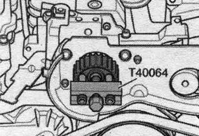
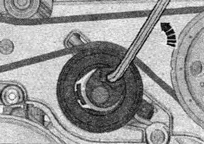
4. Toothed pulley of the fuel injection pump: remove using the puller "T40064".
5. Roller.
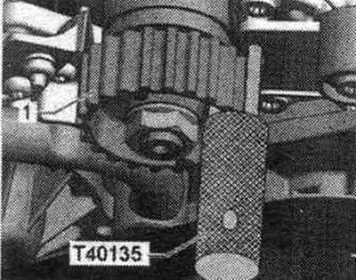
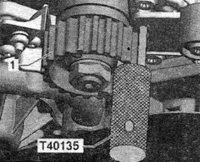
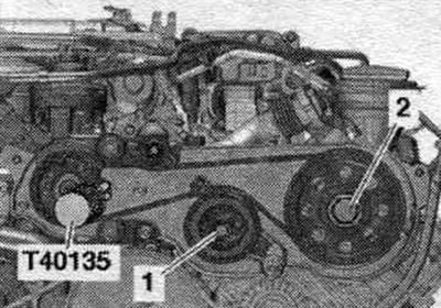
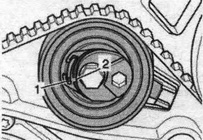
6. Fuel injection pump drive toothed belt: before removing, mark the direction of travel with chalk or a felt-tip pen - changing the direction of travel of a previously used toothed belt may lead to damage; check the degree of wear. Before putting on the timing belt, the following points must be completed. The crankshaft TDC must coincide with the camshaft TDC. In addition, the fuel injection pump toothed belt pulley must be held in place by the "T40135" retainer. (It is important to prevent the timing belt from swinging!).
7. Bolt: 9 Nm.
8. Rear timing belt cover.
9. Timing belt tension roller.
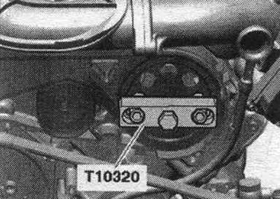
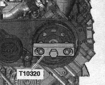
10. Drive gear of the toothed belt: remove using the puller "T10320".
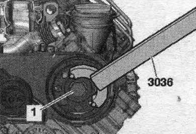
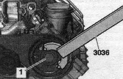
11. Bolt: 75 Nm; for unscrewing and tightening use counter support "3036".
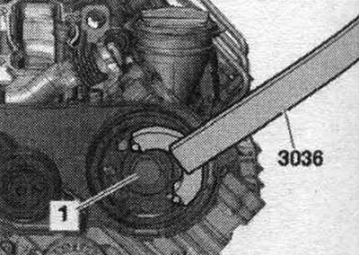
12. Bolt: 23 Nm.
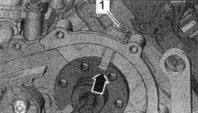
TDC in crankshaft "1"
TDC in the camshaft "arrow"
Fixing tool "T40135" for the fuel injection pump toothed belt pulley
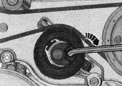
Remove the injection pump toothed pulley
Remove the fuel injection pump toothed belt pulley using the T40064 puller.
Loosen and tighten the center bolt of the timing belt drive sprocket
To loosen and tighten the central bolt "1" use the counterstop "3036".
Remove the drive pulley of the timing belt
Using the T10320 puller, remove the timing belt pulley.
Removal and installation the fuel injection pump toothed belt
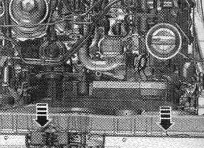
Remove the upper part of the intake manifold. Turn the timing belt cover forward of the arrow and hang the bracket on the bottom of the timing belt cover. For clarity, the timing belt guard is shown with the top of the intake manifold removed.
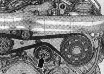
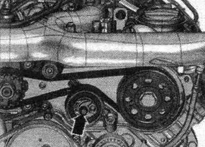
Unscrew the bolt "arrow" of the timing belt tension roller by approximately 2 turns.
Unscrew bolt "1" of the drive pulley of the toothed belt by approximately 2 turns, using counter support "3036" for this.
Remove the timing belt drive pulley using the T10320 puller. The timing belt drive pulley remains on the camshaft. Remove the toothed belt first from the injection pump toothed belt pulley, and then from the drive toothed belt pulley.
Install
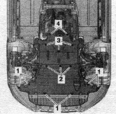
Installation in reverse order. Remove the noise insulation screens by loosening the fastening elements "1...4".
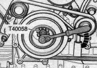
Insert the guide pins of the adapter "T40058" as shown below: the large diameter "arrow 1" faces the engine, the small diameter "arrow 2" faces the adapter.
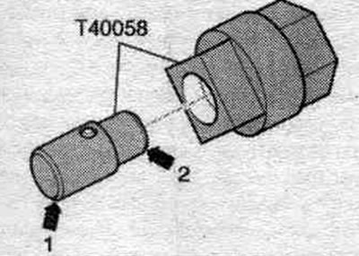
Risk of damage due to jumping of the camshaft drive chain. Rotate the crankshaft only in the direction of engine rotation "arrow". Turn the crankshaft with the adapter "T40058" to the "TDC" position.
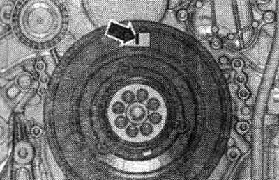
The "arrow" marking must be vertical to the center of the crankshaft, as shown in the figure. Remove the air duct hose.
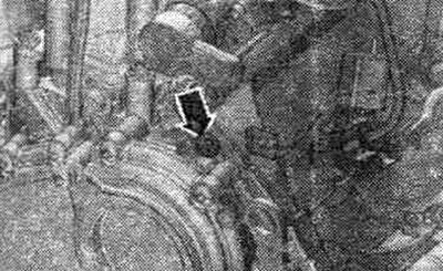
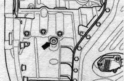
Unscrew the rear plug "arrow" of the right cylinder head. For a better view, see the installation. the position with the engine removed is shown from the rear.
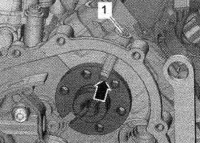
Check whether hole "1" of the plug and the groove "arrow" in the camshaft flange are visible. To do this, simply shine a small flashlight into the hole in the plug. For better presentation, the camshaft flange is shown without the chain drive and without the drive chain cover.
If the groove is not located under the hole, the crankshaft should be turned 360 degrees in the direction of engine rotation. Unscrew the screw plug "arrow" on the top of the oil. pallet.
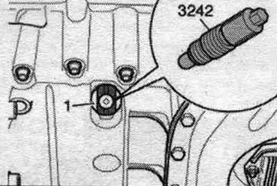
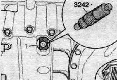
Risk of injury when probing the "TDC" hole with your finger. Do not turn crankshaft "1." Tighten the "3242" locking bolt into the hole with a torque of 20 Nm. If necessary, rotate the crankshaft slightly in both directions to fully center the bolt. Before installing the timing belt, it is necessary to firmly secure the fuel injection pump and timing belt pulley.
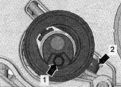
Lock the high-pressure pump toothed belt sprocket with the locking device "T40135". Before fitting the toothed belt, the high-pressure pump toothed belt pulley must be held by the retainer "T40135" (It is important to prevent the timing belt from swinging!).
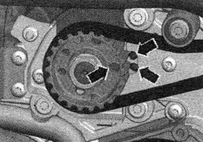
The hole - the arrow in the toothed belt - is located -at the 3 o'clock position-.
The T40135 locking tool must be fully inserted.
Check the installation. tension roller position. The locking tab "arrow 2" should fit into the groove of the fuel injection pump bracket. The tension roller should be loosened, with the hexagonal hole "arrow 1" facing downward. Install the timing belt.
Tighten bolt "1" of the toothed belt tension roller without applying force so that the eccentric of the toothed belt tension roller can still be turned without tipping over. Tighten bolt "2" of the drive pulley of the toothed belt so that the drive pulley of the toothed belt can still be turned without tipping over.
Tighten the timing belt tensioner pulley using a hex key in the direction of the arrow until the hex hole is at the 1 o'clock position. Never turn the tensioner pulley past the 12 o'clock position.
Then relieve the tension roller of the toothed belt "arrow" so that the hexagonal hole is in the -3 o'clock position-.
Tighten the timing belt tension roller from the 3 o'clock position so that protrusion "1" and notch "2" are exactly opposite.
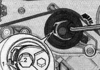
While holding the timing belt tension roller in this position, tighten the bolt "arrow".
Tighten bolt "1" of the drive pulley of the toothed belt, for this use counter support "3036".
Unscrew the locking bolt "3242". Screw the threaded plug "arrow" for the "TDC" mark into the upper part of the oil. pan. Insert the guide pins of the "T40058" adapter as shown below: the large diameter "arrow 1" faces the engine, the small diameter "arrow 2" faces the adapter. Risk of damage due to jumping of the camshaft drive chain. Turn the crankshaft only in the direction of engine rotation "arrow".
Rotate the crankshaft with the "T40058" adapter by 1 revolution. Check the timing belt tension: protrusion "1" should be opposite notch "2." If the specified value is not reached, readjust the timing belt tension.
Installation in reverse order. Install the upper intake manifold.
(The original article is available on the online resource AudiManual.ru)