Repair Chevrolet Repair Toyota Repair Honda Repair AvtoVAZ Repair Mercedes-Benz Repair BMW Repair Opel
Home  |  Contacts  |  Sitemap  |    
English Русский
Български
Беларускі
Український
Српски
Hrvatski
Română
Polski
Slovenský
Magyar
AudiManual.ru


  • AUDI 80
  • AUDI 100
  • AUDI A3
  • AUDI A4
  • AUDI A6
  • AUDI A8
  • AUDI Q
  • OTHER
  • ARTICLES
B8 (2007-2015) B7 (2004-2008) B6 (2000-2006) B6 (2000-2006, petrol) B5 (1994-2001) B5 (1994-2001, petrol)

Injection system — removal and installation of injectors (Audi A4 B8)

  • Home
  • Audi A4
  • B8 (2007-2015)
  • Power unit
  • Diesel engines 2.7/3.0 l
  • Injection system — removal and installation of injectors
            0
Note: The following shows the removal and installation of the injector on cylinder bank 2 on the left. For cylinder bank 1 only: remove the upper part of the air injector. filters with air flow meter. On cylinder bank 2, it is necessary to unscrew the coolant expansion tank; the coolant lines remain connected.


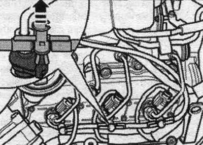
Remove the engine cover. Mark the compatibility of the injectors with the cylinder. Reinstallation is only permitted on the same cylinder. When working on the system. when injecting, observe the rules for maintaining cleanliness. Immediately close open connections with a special cap. Remove the return line hoses from the injectors by pressing both covers down and simultaneously pulling up on the intermediate element to release the "arrow." Disconnect the plug-in connectors on the injectors to be removed.

Remove the engine cover. Mark the compatibility of the injectors with the cylinder. Reinstallation…


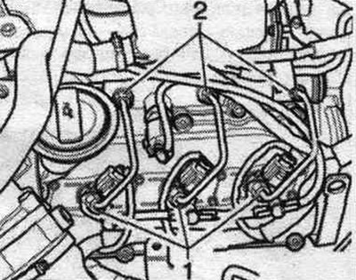
Loosen the union nuts securing the high-pressure lines "1" to the injectors using the "T40055" socket. Use the appropriate socket on the wrench to loosen the union nuts on the high-pressure fuel lines. ramp. Completely loosen the union nuts, carefully remove the high-pressure lines, and place them on a clean rag.


Loosen the union nuts securing the high-pressure lines «1» to the injectors using the «T40055»…


Unscrew the "arrow" injector caps. Pull the caps up and turn them 90°.

Unscrew the «arrow» injector caps. Pull the caps up and turn them 90°.


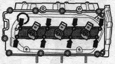
Loosen the clamps of the "arrow" injectors.

Loosen the clamps of the «arrow» injectors.


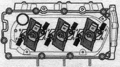
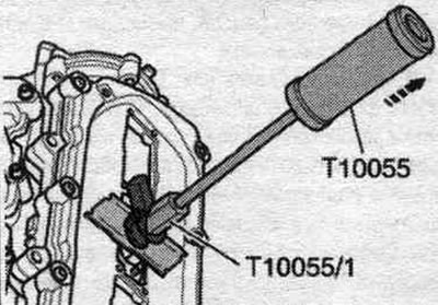
Remove the injectors using the T10055 puller and the T10055/1 adapter. Place the removed injectors on a clean rag.

Remove the injectors using the T10055 puller and the T10055/1 adapter. Place the removed injectors…


Installing new injectors


When installing a new injector, it is necessary to replace: clamp, copper seal. ring, sealing ring of the injector socket, sealing ring of the return line fitting. When reusing high-pressure lines, observe the corresponding cylinder designations. High pressure lines can be reused after the following checks. Check the sealing cone of the corresponding high-pressure line for deformations and cracks. The hole must not be deformed or damaged. Lines with corrosion should not be reused.


Installation of previously used injectors


When reinstalling a used injector, the following must be replaced: clamp, copper seal. ring, sealing ring of the injector socket, sealing ring of the return line fitting. Apply rust remover spray to the injector needle. After about 5 minutes, remove any soot or oil particles with a rag. If the nozzle is heavily contaminated, its lower part should be additionally cleaned. clean with a soft brass brush to facilitate removal of the copper seal (do not allow the brass brush to come into contact with the injector nozzle channel). To remove the old copper gasket from the injector, carefully clamp the gasket in a vice so that it is clamped between the clamping jaws directly when turning. Using light twisting and pulling movements of your hand, remove the nozzle from the copper gasket. Use a scraper to clean off any deposits under the copper seal. ring. Using a plastic bushing, install a new copper seal. ring. Before installation, lubricate all seals. rings with mounting or oil. Risk of damage to the sealing surface of the injector. To remove soot particles from the injector sealing surface, clean the injector seat in the cylinder head with a rag soaked in oil or rust remover. Install the injectors. Tighten the high pressure fuel line union nuts by hand without tightening. Pay attention to stress-free installation. Tighten the high pressure fuel lines. Carefully install the connecting elements of the return lines onto the injectors using the lip seals and applying pressure (pre-check the lip seal for damage). The lock should click into place, then gently press the release bolt down. After replacing one or more injectors, the ECU must perform a "Fuel Quantity Adjustment (IMA)" and "Voltage Adjustment (ISA)" for the new injectors. Additionally, check all other injectors to ensure that all matching parameters "Injector Performance Matching (IMA)" and "Injector Voltage Matching (ISA)" are entered correctly. If the correct matching parameters are entered into the engine control unit memory, they should not be re-entered under any circumstances.


Pump fuel. system and check for leaks


To remove air, do not open the high pressure outlets, air from the fuel. the system goes away on its own. Let the engine run at idle for a few minutes. move and then turn it off again. Turn off the ignition. Check all fuel. system and connection of return fuel. highways (6 pcs.) for leaks. If the seal is broken despite the correct tightening torque, replace the faulty unit. Replacement of return lines is carried out only in a set with a pressure reducing valve. Carry out a test drive with at least one acceleration under maximum load and then recheck the high-pressure circuit for leaks. Presence of air in fuel. system during a test drive may cause the engine to operate in emergency mode. Turn off the engine and clear the fault memory. Continue with the test drive.

[The article is a reprint of material from: AUDIMANUAL.RU]
The article was checked by auto expert Timur Bazhenov
This article is available at russian, bulgarian, belarusian, ukrainian, serbian, croatian, romanian, polish, slovak, hungarian

Share information:
Previous articles
Audi A4 B8: Diesel engines 2.7/3.0 l
Next articles

Injection system — high-pressure fuel pump (CAPA)
Injection system — high-pressure fuel pump (CAMA, CAMB, CCWA,…
Injection system — toothed belt (CAPA)
Injection system — toothed belt (CAMA, CAMB, CCWA, CCWB, CGKA,…
Injection system — Lambda probes and exhaust gas temperature…
Injection system — Lambda probes, exhaust gas temperature…
Exhaust system — muffler
Exhaust system — exhaust manifold


Similar articles on other Audi car models:
Fuel injection system parts — removal and installation Audi 80 B3 (1986-1991, petrol)
Fuel injector of MPI and MPFI injection system — removal and… Audi 100 C4 (1990-1994)
Removal and installation of fuel lines and injectors (petrol) Audi A3 Type 8L (1996-2003)
Removal and installation valve injectors Audi A6 C4 (1994-1997)
Removal and installation of the exhaust system Audi A8 D2 (1994-2002)
Removal and installation of sensors and some lines of the engine… Audi Q7 Typ 4L (2005-2015, diesel)
Removal and installation the cooling system pump Audi A2 (1999-2005)
Link to this page in different formats


Visitor comments

No comments yet


How much will 28 + 31 =


A4(B8, 2007-2015) 
  • General information
  • Operating instructions
  • Power unit
  • Petrol engines 1.8 l
  • Petrol engines 1.8/2.0 l
  • Petrol engines 3.0 l
  • Petrol engines 3.2 l
  • Fuel system (petrol)
  • Diesel engines 2.0 l (CA*)
  • Diesel engines 2.0 l (CJCB)
  • Diesel engines 2.7/3.0 l
  • Diesel engines 3.0 l
  • Fuel system (diesel)
  • Transmission
  • Manual gearbox 0B1
  • Manual gearbox 0B2
  • Manual gearbox 0B3
  • Manual gearbox 0B4
  • Automatic transmission 0B5
  • Automatic transmission 0B6
  • Automatic transmission 0AW
  • All-wheel drive system
  • Chassis
  • Front suspension
  • Rear suspension
  • Brake system
  • Steering system
  • Body
  • Exterior
  • Interior
  • Seats
  • Doors, locks and windows
  • Security system
  • Heating and air conditioning
  • Electrical equipment
  • Audio system
  • Power devices
  • Equipment and devices
  • Lighting and lamps
  • Electrical circuits
 
A4(B7, 2004-2008) 
  • General information
  • Introduction to manual
  • Troubleshooting
  • Operating instructions
  • Maintenance
  • Power unit
  • Petrol engines 2.0 (ALT)
  • Petrol engines 2.0 (TFSI)
  • Petrol engines 1.8 (MPI)
  • Diesel engines
  • Cooling system
  • Air conditioner
  • Fuel and exhaust system
  • Ignition system
  • Starting and charging
  • Transmission
  • Clutch
  • Manual gearbox
  • Automatic gearbox
  • Drive shafts
  • Chassis
  • Brake system
  • Front suspension
  • Rear suspension
  • Steering
  • Body
  • Exterior
  • Interior
  • Electrical equipment
  • Equipment and devices
  • Lighting and signaling
  • Windscreen wipers and washers
  • Electrical diagrams
  • Electrical diagrams (since 2007)
 
A4(B6, 2000-2006) 
  • General information
  • Vehicle Description
  • User manual
  • Maintenance
  • Power unit
  • Gasoline engine
  • Diesel engine
  • Lubrication system
  • Cooling system
  • Supply system
  • Injection system
  • Exhaust system
  • Ignition and control
  • Transmission
  • Gear box
  • Clutch and drive shafts
  • Chassis
  • Brake system
  • Car suspension
  • Steering
  • Body
  • Heating and ventilation
  • Exterior (external elements)
  • Interior (internal elements)
  • Electrical equipment
  • Power devices
  • Lighting and appliances
  • Electrical circuits
 
A4(B6, 2000-2006, petrol) 
  • General information
  • Introduction to the guide
  • Car care
  • Power unit
  • Engine repair
  • Lubrication system
  • Cooling system
  • Injection and control system
  • Ignition system
  • Power and exhaust system
  • Transmission
  • Clutch and drive shafts
  • Car gearbox
  • Chassis
  • Suspension and wheels
  • Steering
  • Brake system
  • Body
  • Interior
  • Exterior
  • Electrical equipment
  • Equipment and devices
  • Lighting and signaling
  • Power devices
  • Electrical circuits
 
A4(B5, 1994-2001) 
  • General information
  • Introduction to the guide
  • Car care
  • Maintenance (gasoline)
  • Maintenance (diesel)
  • Power unit
  • Gasoline engines
  • Diesel engines
  • Engine overhaul
  • Cooling system
  • Fuel injection (gasoline)
  • Fuel system (diesel)
  • Exhaust system
  • Ignition system
  • Transmission
  • Clutch
  • Mechanical gearbox
  • Automatic gearbox
  • Drive shafts
  • Chassis
  • Brake system
  • Car suspension
  • Steering
  • Body
  • Exterior
  • Interior
  • Doors, locks and windows
  • Heating and ventilation
  • Electrical equipment
  • Power devices
  • Equipment and devices
  • Electrical circuits
 
A4(B5, 1994-2001, petrol) 
  • General information
  • Vehicle description
  • Maintenance
  • Power unit
  • Engine repair
  • Turbocharging
  • Exhaust system
  • Cooling system
  • Ignition system
  • Fuel system
  • Motronic injection system
  • MPI and MPFI injection system
  • Transmission
  • Clutch
  • Gearbox and shafts
  • Chassis
  • Steering
  • Car suspension
  • Brake system
  • Wheels and tires
  • Body
  • Heating and ventilation
  • Body parts
  • Electrical equipment
  • Fuses and relays
  • Power devices
  • Lighting and lamps
  • Tools and devices
  • Electrical circuits
 
AudiManual.ru © 2017-2026 · Mobile version · Feedback · Sitemap: EN BG BY UA RS HR RO PL SK HU · Site search · News and articles
80 B2 · 80 B3 petrol · 80 B3 · 80 B4 · 100 C3 diesel · 100 C3 petrol · 100 C3 · 100 C4 petrol · 100 C4 · A3 Type 8L · A4 B5 petrol · A4 B5 · A4 B6 petrol · A4 B6 · A4 B7 · A4 B8 · A6 C4 · A6 C5 · A6 C5 Allroad · A8 D2 · Q5 Type 8R · Q7 Typ 4L · Audi A2 ·
This site uses cookies 🍪. Click the button to accept this fact.