
Table of contents: Muffler ↓ Removal and installation the diesel… ↓
Muffler
Vehicles without SCR catalyst
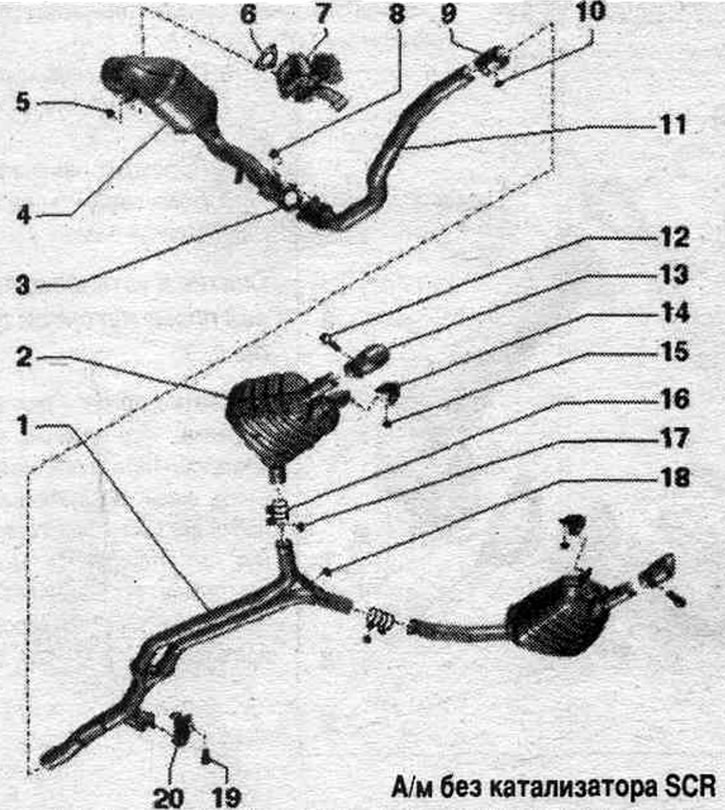
1. Y-pipe: Factory installed as one piece with the rear mufflers; in case of repair of the tee, main muffler and muffler end, replace them separately; the junction between the tee and the end muffler; align the system. exhaust gas release without mechanical stress.
2. Main muffler: The factory-installed unit has a tee; in case of repair of the tee, main muffler and muffler end, replace them separately.
3. Gasket: replace.
4. Diesel particulate filter: with catalyst; with the pressure line of the exhaust gas pressure sensor 1 "G450"; after replacement, carry out adaptation in the "Guided functions" mode.
5. Nut: replace; lubricate with heat-resistant paste; 23 Nm.
6. Gasket: replace.
7. Turbocharger.
8. Nut: replace; 23 Nm.
9. Double clamp, front: align the system before tightening. exhaust gas outlet without mechanical stress; tighten the connections evenly.
10. Nut: 23 Nm.
11. Downpipe: with detachable element; the detachable element must not be bent more than 10° - risk of damage; protect from impacts and shocks; the exhaust system should be freely aligned with the cut area.
12. Bolt: 23 Nm.
13. Exhaust pipe: replace.
14. Suspension mount: replace if damaged; check pre-tension.
15. Nut: 20 Nm.
16. Rear clamp: For replacing the main muffler tee individually.
17. Nut: 23 Nm.
18. Nut: replace; 23 Nm.
19. Bolt.
20. Suspension mount: replace if damaged; check pre-tension.
Cars with SCR catalyst
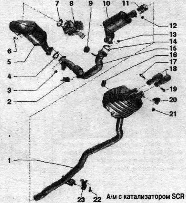
1. Main muffler.
2. Nozzle for reducing agent "N474".
3. Nut: replace; lubricate with heat-resistant paste; 23 Nm.
4. Gasket: replace.
5. Diesel particulate filter: with catalyst; with the pressure line of the exhaust gas pressure sensor 1 "G450"; after replacement, carry out adaptation in the "Guided functions" mode.
6. Nut: replace; 23 Nm.
7. Gasket: replace.
8. Turbocharger.
9. Fastening loop.
10. SCR catalyst.
11. Clamp clamp.
12. Nut: 23 Nm.
13. Nut: replace; lubricate with heat-resistant paste; 23 Nm.
14. Gasket: replace.
15. Intake pipe.
16. Fastening loop.
17. Bolt: 23 Nm.
18. Exhaust pipes.
19. Nut: 20 Nm.
20. Bolt: 23 Nm.
21. Suspension mount: replace if damaged; check pre-tension.
Suspension elements of the intake pipe
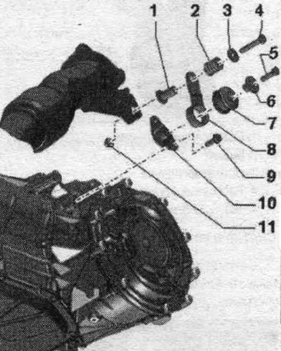
1. Expansion sleeve. 2. Pressure spring. 3. Washer. 4/5. Bolt. 23 Nm. 6. Spacer sleeve. 7. Buffer. 8. Pad. 9. Bolt. 23 Nm. 10. Bracket. 11. Nut.
Elements of the front suspension system. exhaust gas release
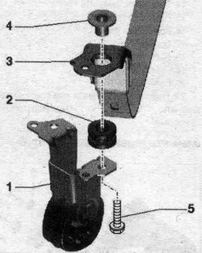
1. Hanging mount. 2. Buffer. 3. Tension bar. 4. Expansion sleeve. 5. Bolt 20 Nm.
Removal and installation the diesel particulate filter
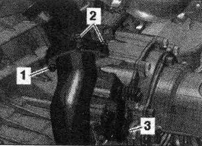
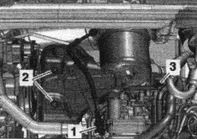
Remove rear noise insulation "2". Unscrew nut "1". Nuts "2" are removed later. "Pos. 3" should not be taken into account.
Remove the stretch. Remove the front wall of the water drainage box.
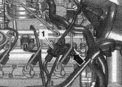
Remove the engine cover. Remove the G39 lambda probe electrical connector "1" from its holder and disconnect it. Release the wire. Ignore the "arrow".
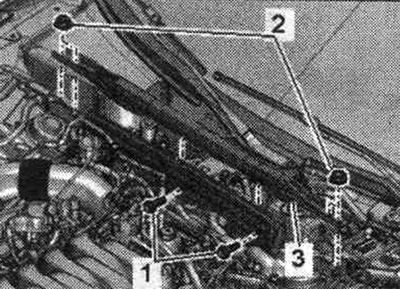
Vehicles with SCR catalytic converter: Disconnect plug connector "1". Disconnect NOx sensor control unit "J583" "pos. 2" from the bracket and release. "Pos. 3" should not be taken into account.
All
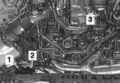
Release and disconnect connector "1" from the exhaust gas temperature sensor. Remove bolts "2" and "3". Remove the turbocharger heat shield.
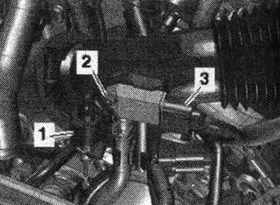
Disconnect plug connector "1" and release the wire. Disconnect plug connector "3". Unscrew screw "2" and release exhaust gas pressure sensor 1 "G450".
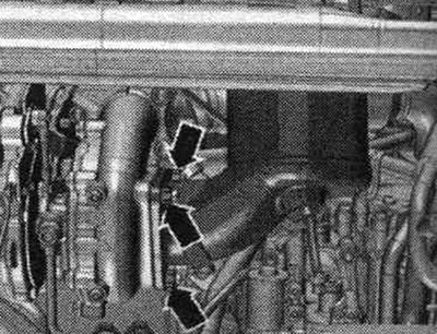
Unscrew the arrow nuts and remove the diesel particulate filter from the turbocharger.
Unscrew the nuts "2" accessible from above and remove the diesel particulate filter. "Pos. 3" should not be taken into account.
Install
Installation in reverse order. Replace all seals, gaskets and self-locking nuts. Install the turbocharger heat shield. Connect the exhaust gas temperature sensor connectors. Install the front wall of the water drain box. Align the system. exhaust gas release without mechanical stress. Install soundproofing.
(The original material is located on the website AudiManual.ru)