
Table of contents: Nozzle for reducing agent "N474" ↓ Active tank for reducing agent with… ↓ Recovery pump "V437" ↓ Support cup of the restorer ↓ Passive tank for reducing agent with… ↓
Nozzle for reducing agent "N474"
1. Bolt: 5 Nm. 2. Mounting clamp. 3. Gasket: replace. 4. Nozzle for reducing agent "N474". 5. Reducing agent hose; to detach, press the release tabs. 6. Electrical connector. 7. Intake pipe.
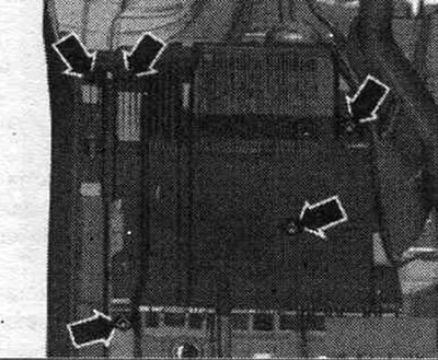
Disconnect the recovery fluid lines
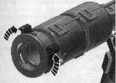
To disconnect the recovery lines, press the release tabs in the direction of the arrow.
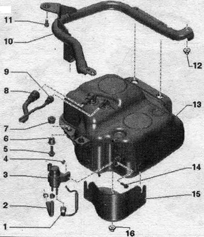
Active tank for reducing agent with attachments
Installation location: at the height of the rear seat, on the left under the bottom.
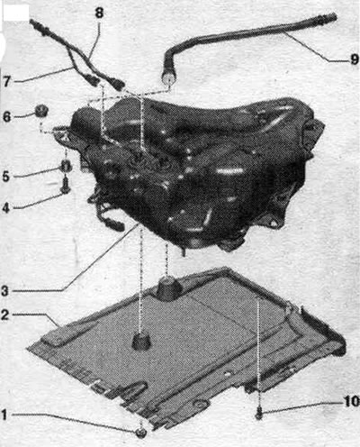
1. Nut: 2 Nm. 2. Cover of the active reservoir for the reducing agent. 3. Active reducing agent tank. 4. Bolt: 20 Nm. 5. Bushing. 6. Nozzle. 7. Transfer line: from the transfer pump of the reducing agent "V436" to the absorber. 8. Ventilation line: from the neck. 9. Filling line: from the filler neck. 10. Bolt: 4.2 Nm.
Emptying the active tank for the reducing agent
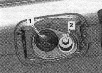
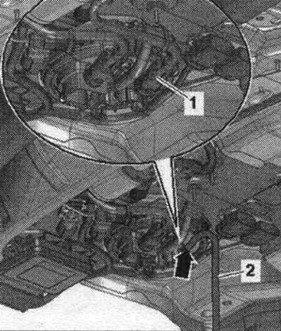
Open the fuel hatch. tank. Unscrew cap "2" of the filler neck of the reducing agent. "Pos. 1" should not be taken into account.
Unscrew the bolts and nuts of the "arrows", remove the cover of the active tank.
Place a drain pan under the hole. Disconnect the return fuel line "1" from the support bowl by pressing the release buttons. Attach auxiliary hose "2" to the "arrow" branch pipe of the support bowl and drain the reducing agent into the receiving container. Close open lines and pipes with clean plugs from the VAS 6122 engine plug kit.
After filling, the following must be done: adaptation of the training value after draining the reducing agent or replacing parts.
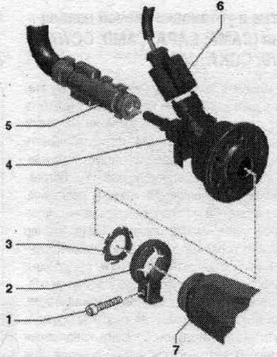
Recovery pump "V437"
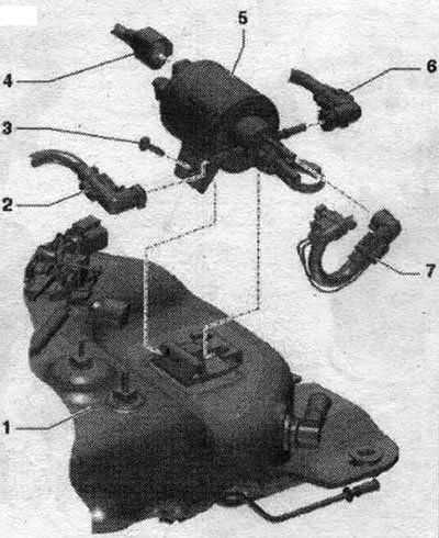
1. Active reducing agent tank. 2. Return line: with heater. 3. Bolt: 2 Nm. 4. Electric cable: version depending on the version for the country. 5. Pump for feeding reducing agent "V437": with heating element of pump for feeding reducing agent "Z103"; with system pressure sensor. dosage of reducing agent "G686". 6. Discharge line: with heater. 7. Dosing line: from the pump for the reducing agent "V437" to the nozzle for the reducing agent "N474"; with a heater; clip onto the top. tank.
Support cup of the restorer
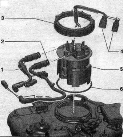
1. Return line: with heater. 2. Discharge line: with heater. 3. Union nut: replace; remove and install using the T50014 tool. 4. Electrical connectors: G684 reducing agent level sensor, G685 reducing agent temperature sensor, Z102 reducing agent tank heating element. 5. Support bowl: with G684 reducing agent level sensor, G685 reducing agent temperature sensor, Z102 reducing agent tank heating element, and filter. 6. Lip seal: replace; install dry.
Passive tank for reducing agent with attachments
Installation location: rear on the bottom.
1. Transfer line: to the active tank; clip onto the top. tank. 6. Bushing. 7. Nozzle. 8. Filling line. 9. Ventilation line: to the filler neck; clip onto the top. tank. 10. Mounting frame of the passive tank. 11. Bolt: 20 Nm. 12. Nut: 20 Nm. 13. Passive reservoir of the reducing agent. 14. Bolt: 1.8 Nm. 15. Cover: transfer pump of the reducing agent "V436". 16. Nut: 2.1 Nm.