
Table of contents: Intake manifold ↓ Removal and installation the upper… ↓ Lower left intake manifold - removal… ↓ Lower right intake manifold -… ↓
Intake manifold
The illustration shows the top of the intake manifold and the lower left side of the intake manifold.
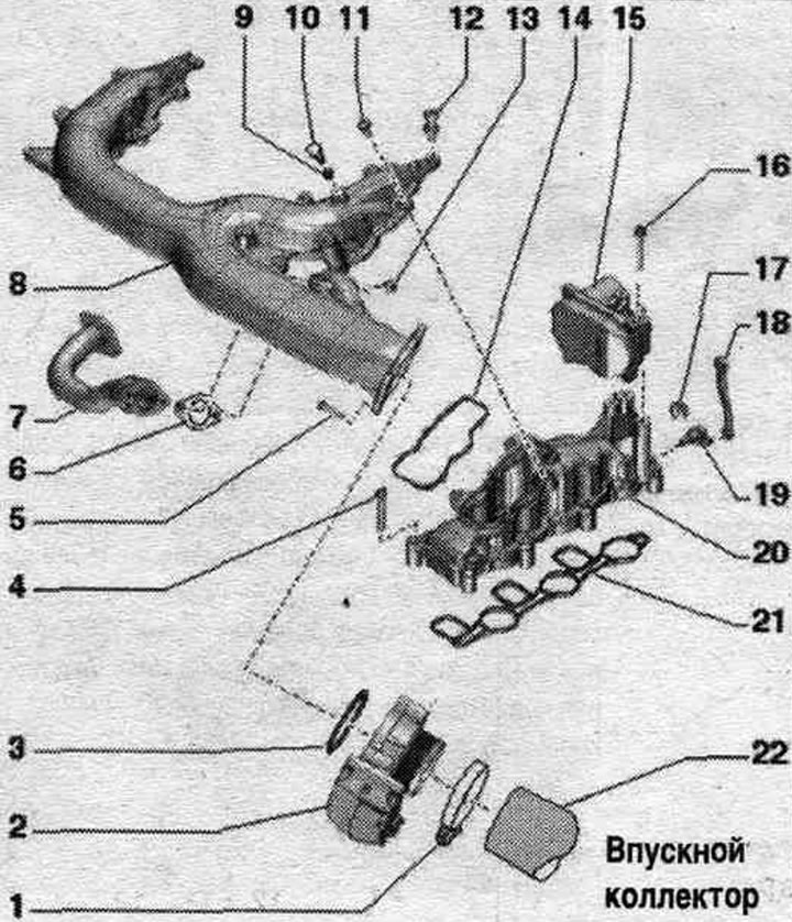
1. Fastening clamp: 5.5 Nm; reinforced.
2. Throttle control unit "J338": 9 Nm.
3. Sealing ring: replace.
4. Bolt: 9 Nm; tighten in stages, crosswise.
5. Bolt: 9 Nm.
6. Gasket: replace.
7. Connecting tube of the system. exhaust gas recirculation.
8. Upper part of the intake manifold.
9. Lip seal: replace.
10. Threaded plug: 10 Nm.
11. Bolt: 9 Nm.
12. Engine casing guide pins: 5 Nm.
13. Bolt: 9 Nm.
14. Gasket: check, replace if damaged.
15. Intake manifold flap motor: Cylinder bank 1 (right): Intake manifold flap motor "V157"; bank 2 (left): V275 intake manifold flap motor.
16. Bolt: 10 Nm.
17. Locking clamp.
18. Connecting rod.
19. Leash.
20. Lower part of the intake manifold.
21. Gasket: check, replace if damaged.
22. Air hose: must be cleaned of oil and grease before installation.
Removal and installation the upper part of the intake manifold
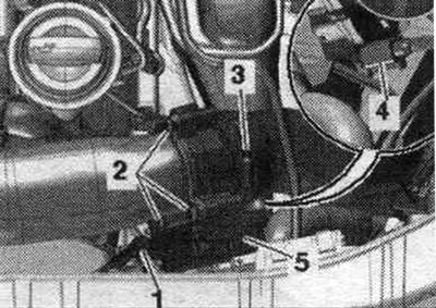
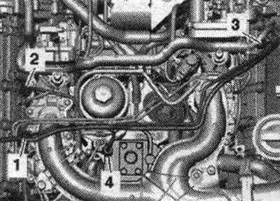
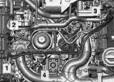
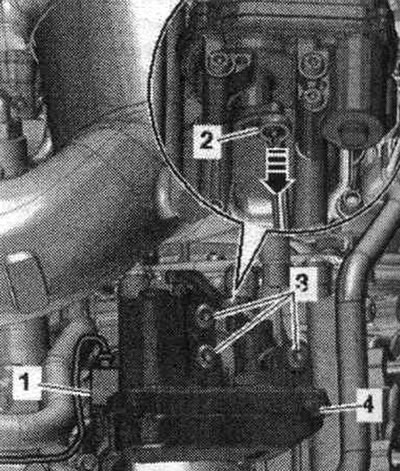
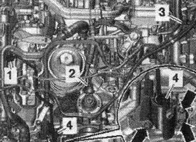
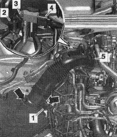
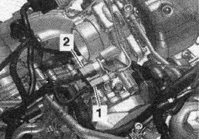
Remove the engine cover. Remove the oil level dipstick "1" from the guide tube. Remove the air duct hose by loosening the hose clamp "3". Loosen the bolt "2" and disconnect the plug connector "4". Remove the throttle valve module "J338" "pos. 5".
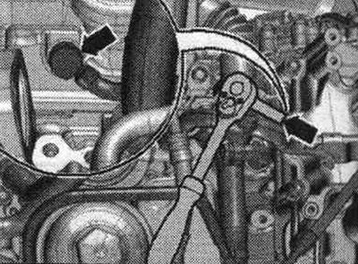
Unscrew the "arrow" bolts and remove the engine suspension eye "1" from the front left.
CAMA, CAMB, CCWA, CCWB, CGKA, CGKB, CCLA: Unscrew the "arrow" screws and remove the clamps. Unscrew union nuts "1" and "4" and remove the high pressure line. "Pos. 2, 3" do not take into account.
CAPA: Unscrew union nuts "1" and "3". Loosen and remove the high-pressure lines. "Pos. 2" should not be taken into account.
All
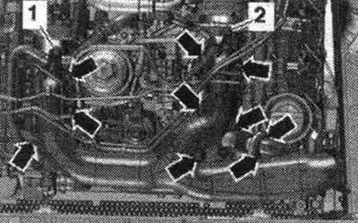
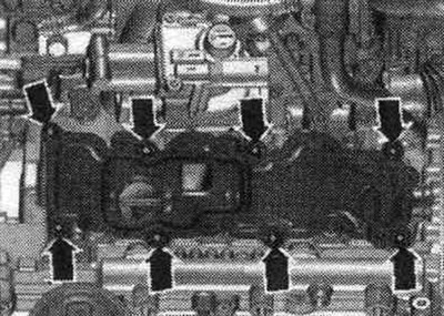
Loosen engine casing guide pins "1" and "2". Loosen bolts "arrows" and remove the upper part of the intake manifold.
Install
Installation in reverse order. Replace all gaskets and seals. rings. Hoses and hose fittings syst. air boosters must be cleaned of oils and grease before installation.
CAMA, CAMB, CCWA, CCWB, CGKA, CGKB, CCLA: Install high pressure line.
Lower left intake manifold - removal and installation
CAMA, CAMB, CCWA, CCWB, CGKA, CGKB, CCLA: Unscrew the "arrow" screws and remove the clamps. Unscrew the union nuts "1...4" and remove the high-pressure lines.
CAPA: Unscrew union nuts "1" and "3". Loosen and remove the high-pressure lines. "Pos. 2" should not be taken into account.
All
Remove the upper part of the intake manifold. Carefully press the connecting rod "2" in the direction of the arrow from the intake manifold flap motor 2 V275- "arrow" (follow the instructions). Carefully press the connecting rod away from the ball joint (danger of fracture). Disconnect connector "1". Loosen bolts "3" and remove the intake manifold flap drive motor "V275" "pos. 4". Disconnect the glow plug connectors of cylinders 4, 5, 6. Remove the radiator changeover valve system. eGR valve "N345" "1" from bracket.
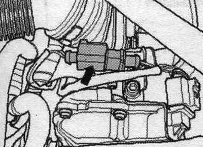
CAPA, CAMA and CAMB: Unscrew the hollow bolt "arrow" of the tube for bleeding the system. cooling, use the hinge housing for this purpose.
CCWA, CCWB, CGKA, CGKB, CCLA: Unscrew bolt "4".
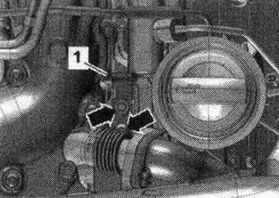
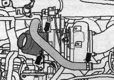
Loosen the clamp "arrow" and remove the tube "1" of the exhaust gas recirculation system.
All
Unscrew the "arrow" bolts. Move the system bleed tube away. cooling to the side and remove the lower part of the intake manifold on the left by moving it forward. The cylinder head intake channels should be covered with a clean rag.
Install
Installation in reverse order. Replace all gaskets and seals. rings. Before installing the lower part of the intake manifold, it is necessary to screw in the hollow bolt of the bleed tube. cooling with a new seal for 2...3 turns (only CAPA, CAMA, CAMB). Tighten the hollow bolt of the bleeder tube. cooling torque of 1.5 Nm. Install the upper part of the intake manifold. Install fuel. high-pressure lines.
Lower right intake manifold - removal and installation
Remove the engine cover.
CAMA, CAMB, CCWA, CCWB, CGKA, CGKB, CCLA: Unscrew the arrow bolts and remove the high-pressure line protective screen. Unscrew union nuts "1" and "4" and remove the high pressure line. "Pos. 2,3" do not take into account.
CAPA: Unscrew the union nuts "1...4" and remove the high-pressure lines.
Remove and disconnect the "arrow" connector of the exhaust gas temperature sensor 2 "G448" from the bracket.
All
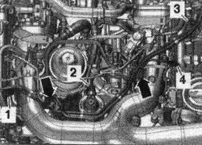
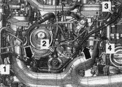
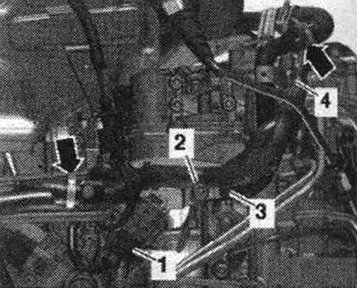
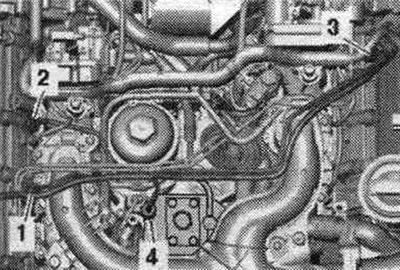
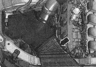
Remove the upper part of the intake manifold. Disconnect plug "1" of the air flow meter "G70". Unscrew bolt "3" and release exhaust gas pressure sensor 1 "G450" "pos. 4" on the air duct pipe. Release connector "2" of exhaust gas temperature sensor 3 for 1 cylinder bank "G496" on the air duct pipe. Remove the air duct hose with the air flow meter "G70" by loosening the hose clamp "5" and opening the clamping clamps "arrows".
Unscrew the bolts -left arrows-, remove the air duct hose -right arrow- and remove the suction pipe with the air duct hose.
Remove the "arrow" air duct.
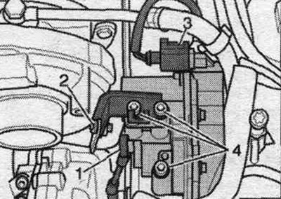
Disconnect connector "2". Unscrew bolts "1".
Remove both plug connectors "1 and 2" from the bracket. Plug connector "2" for CAPA engines is installed in a different location.
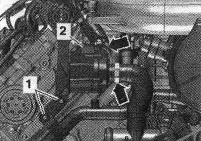
Disconnect plug "3" of the intake manifold flap motor "V157". Carefully press connecting rod "1" in the direction of the arrow away from the intake manifold flap motor "V157" (follow the instructions). Carefully press the connecting rod away from the ball joint (danger of fracture). Bolt "2" is not installed. Unscrew bolts "4". Disconnect the glow plug connectors of cylinders 1, 2. 3. Push the wiring harness aside.
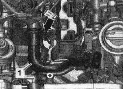
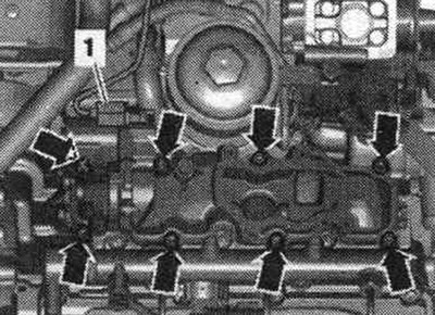
Remove the bolts marked "arrows." Push the coolant pipe aside and remove the lower section of the right intake manifold. "Pos. 1" should not be taken into account. The cylinder head intake channels should be covered with a clean rag.
Install
Installation in reverse order. Replace seals. Install the upper intake manifold. Install fuel. high-pressure lines. Check the fuel tightness. syst..