
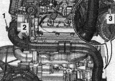
Turbocharger
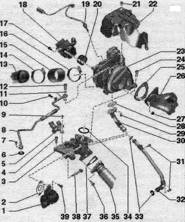
1. Connecting pipe: to the radiator changeover valve of the system. exhaust gas recirculation.
2. Gasket: replace.
3. Intermediate flange.
4. Bolt: 25 Nm.
5. System tube. cooling rear right.
6. Sealing ring: replace.
7. Bolt: 9 Nm.
8. Cylinder block oil supply line.
9/10. Bolt: depending on design; 9 Nm.
11. Sealing rings: replace.
12. Hollow screw: 15 Nm.
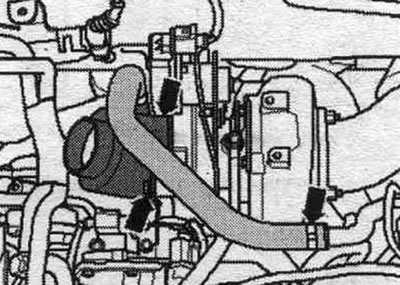
13. Right air tube.
14. Hose clamp: reinforced; 5.5 Nm.
15. Air duct hose: from turbocharger to right air intake.
16. Hose clamp: reinforced; 5.5 Nm.
17. Bolt: 9 Nm.
18. Connecting nipple for air duct hose: from air flow meter "G70" to turbocharger; before installation, clean from oil and grease.
19. Exhaust gas temperature sensor 1 "G235".
20. Lip seal: replace if damaged.
21. Bolt: 9 Nm.
22. Turbocharger heat-insulating shield.
23. Turbocharger: with turbocharger control unit 1 "J724".
24. Bolt: replace, lubricate with heat-resistant paste; 30 Nm + 90°.
25. Gasket: replace.
26. Diesel particulate filter.
27. Nut.
28. Gasket: replace.
29. Bolt: lubricate with heat-resistant paste; pre-tighten to 7 Nm; 9 Nm.
30. Upper part of the oil return line: from the turbocharger.
31. Bolts: 9 Nm.
32. Lower part of the oil return line: to the cylinder block.
33. Sealing rings: replace.
34. Gasket: replace.
35. Intermediate tube.
36. Bolt.
37. Gasket: replace.
38. Bolt: 25 Nm.
39. Bolt.
Take off
Caution! If the turbocharger has mechanical damage (for example, damage to the impeller), it is not enough to simply replace the turbocharger. To prevent further damage, the following steps must be taken. Check the housing and air filter element. filters, as well as air supply hoses for contamination. Check the entire system. charge air supply and intercooler for foreign objects. If in the system. if foreign bodies are detected in the air boost line, clean the air boost lines and replace the intercooler if necessary. For vehicles with an independent heater: remove the stretcher and the front wall of the water drainage box.
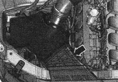
Remove the "arrow" engine cover. Remove the "arrow" air duct.
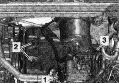
Disconnect plug "1" of the air flow meter "G70". Unscrew bolt "3" and release the exhaust gas pressure sensor 1 "G450" "pos. 4" on the air duct pipe. Release the air duct plug connector "2". Remove the air duct hose with the air flow meter "G70" by loosening the hose clamp "5" and opening the clamping clamps "arrows".
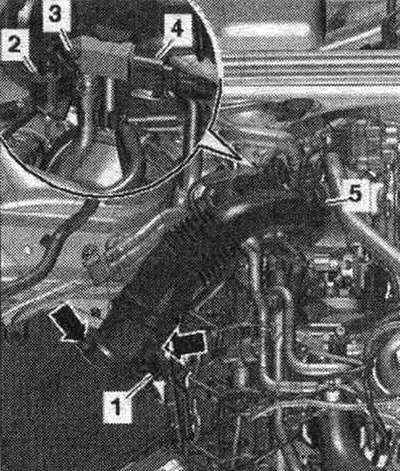
Unscrew bolts "2" and "3". Remove the air duct tube from the air duct hose by loosening clamp "1".
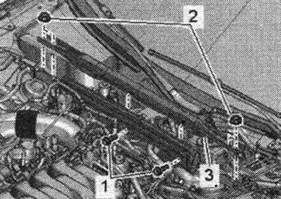
Loosen the bolts - arrows on the left - and set the suction pipe with the connected air duct hose - arrow on the right - aside.
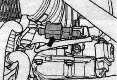
CAMA, CAMB, CAPA: Disconnect plug connector "1" of turbocharger electric motor 1 "V280". Hollow bolt "2" of oil supply line on turbocharger.
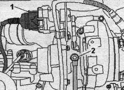
CCLA, CCWA, CCWB, CGKA, CGKB: Disconnect plug "2" of turbocharger electric motor 1 "V280". Loosen bolt "1" and hollow bolt "3" of the oil supply line on the turbocharger.
All
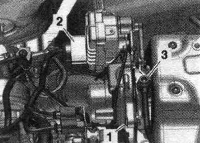
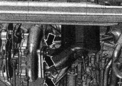
Release and disconnect connector "1" from the exhaust gas temperature sensor. Remove bolts "2" and "3". Remove the turbocharger heat shield.
Disconnect the "arrow" connector of the exhaust gas temperature sensor 1 "G235".
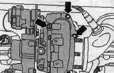
Unscrew the arrow nuts and remove the diesel particulate filter from the turbocharger.
Remove the turbocharger arrow bolts.
Risk of damage to both oil return pipes. The upper part "3" of the oil return line, secured to the turbocharger, must be carefully pulled off the lower part "5" of the oil return line. To prevent bending of both return oil line pipes, remove turbocharger "4" upwards by gently rocking it from side to side.
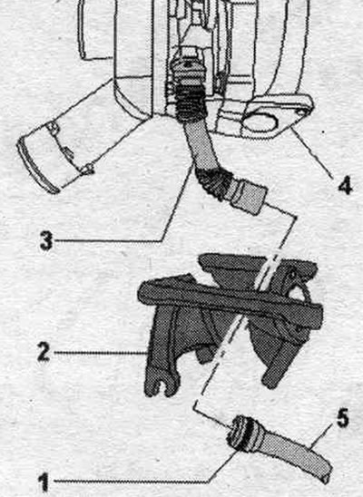
1. Sealing Ring; 2. Intermediate flange.
Remove the turbocharger. Seal the turbocharger openings and boost air ducts with plugs from the VAS 6122 engine plug kit. To avoid damage, do not place the removed turbocharger on top of the oil return line.
Install
Replace gaskets, o-rings and seals. o-rings. When reassembling, install all thermal insulation cuffs where they were originally installed. Fill the turbocharger with oil through the oil supply line nipple. Hose fittings, air tubes and hoses must be cleaned of oil and grease before installation. To secure all hose connections, use clamps of the appropriate series. To ensure that the air duct hoses are securely fastened to the fittings, the engine must be run for approx. To ensure that oil is supplied to the turbocharger, the engine must be run for approx. 1 minute at idle speed; do not give the engine high revs. Install a new seal. ring "1" on the lower part "5" of the return oil line. Lightly lubricate the seal. ring and the inner seating surface at the top of the "3" return oil line. When installing turbocharger "4", pass the upper part "3" of the return oil line through the intermediate flange "2" to the lower part "5" of the return oil line. Risk of damage to seal. rings. Carefully install the upper part "3" of the return oil line onto the lower part "5". Screw on the turbocharger "arrows". Installation is in reverse order. Install a diesel particulate filter. Install the G450 exhaust gas pressure sensor 1. On vehicles with an independent heater, install the front wall of the water drain box.
(The original publication in its entirety is posted on the website AUDIMANUAL.ru)