
Table of contents: Cylinder head cover ↓ Removal and installation the left… ↓ Removal and installation the right… ↓
Cylinder head cover
The figure shows the cylinder head cover of cylinder bank 2 (left).
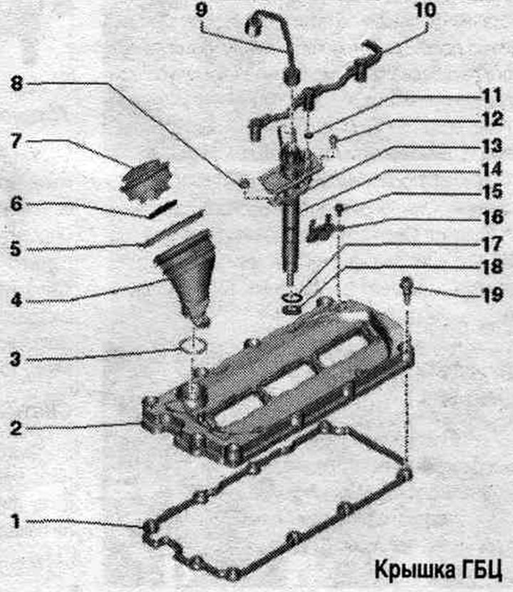
1. Cylinder head cover gasket: replace if damaged or loose.
2. Cylinder head cover.
3. Sealing ring: replace.
4. Oil filler neck: to dismantle, remove the cover, turn the oil filler neck to the left and remove.
5. Lip seal.
6. Lip seal: replace if damaged or loose.
7. Lid.
8. Nut.
9. High-pressure main; mark the compliance with the injection nozzles; do not change the bent shape.
10. Fuel return pipe from the pump injectors.
11. Sealing ring: replace.
12. Bolt.
13. Clamp.
14. Nozzle.
15. Bolt: 5 Nm.
16. Bracket: lambda probe connector "G39".
17. Sealing ring: replace.
18. Copper seal. ring: replace.
19. Bolt: with seal; if damaged or leaking, replace the seal.
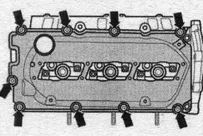
Cylinder head cover - torque and sequence, tightening
Tighten the cylinder head cover "arrow" bolts to a final torque of 9 Nm in stages, crosswise.
Removal and installation the left cylinder head cover
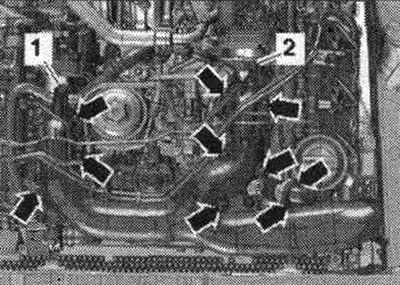
Remove the engine cover "arrows". Remove the upper part of the intake manifold.
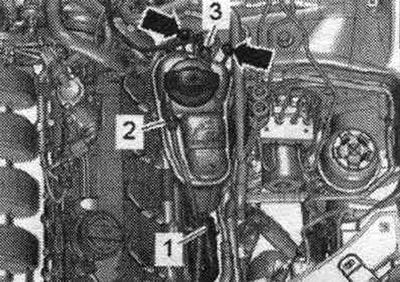
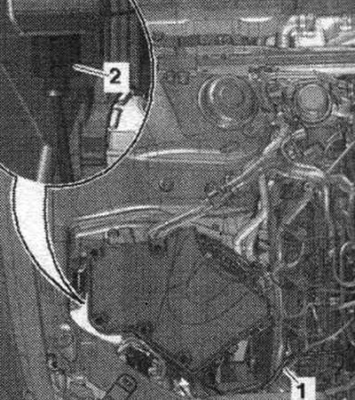
Remove coolant hose "3" from the expansion tank. Unscrew the bolts "arrows" and set the expansion tank with hoses "1" and "2" attached to the side.
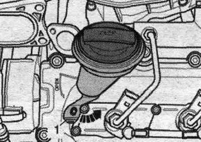
Remove the oil filler neck by lifting the cover "1" and turning the oil filler neck counterclockwise "arrow".
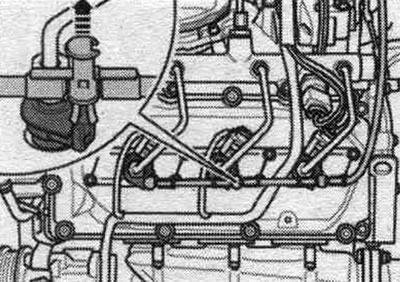
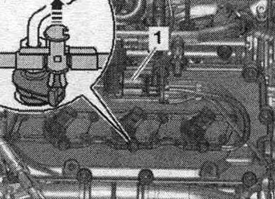
Remove the return fuel pipes. lines from the injection nozzles, to do this, pull the release bolt upwards "arrow".
Remove electrical connector "1" of the lambda probe "G39" from the holder and disconnect it. Release the wire. Unscrew the "arrow" bolts and remove the "G39" lambda probe connector bracket.
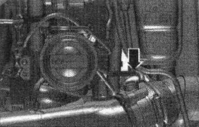
If present, disconnect the vacuum line "arrow".
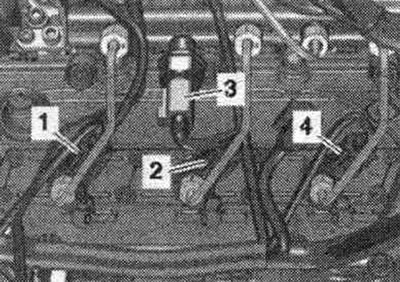
Disconnect the electrical connectors to the glow plugs of cylinders 4 and 5. Disconnect the plug connectors "1...4". Release the wiring harness using the "80-200" release lever.
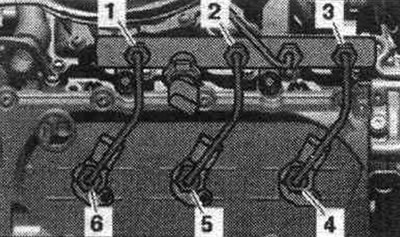
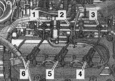
For reinstallation, mark the correspondence of the high pressure lines to the injectors. Loosen the union nuts of the high-pressure lines "1...6" using a 17 mm socket "VAG 1331/6" and heads "T40055" and remove the high-pressure lines.
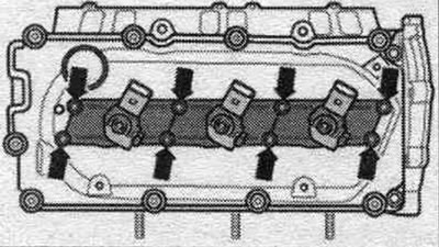
Unscrew the "arrow" bolts of the injector covers. Pull the lids up and turn them 90°.
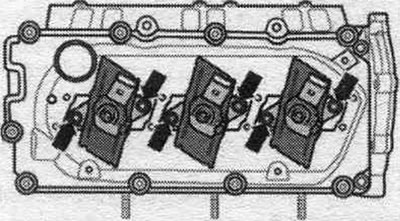
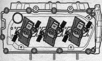
Unscrew the injector "arrow" bolts.
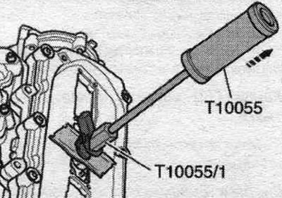
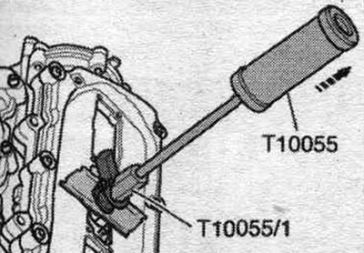
Previously used injectors should only be installed on the same cylinder. Mark the correspondence of each injector to the cylinder. Remove the injection nozzles using the "T10055" puller with the "T10055/1" adapter.
Loosen the cylinder head cover bolts "arrows" crosswise. Unscrew the bolts and remove the cylinder head cover.
Install
Installation in reverse order. Replace the damaged cylinder head cover gasket. Replace the cylinder head cover bolts with a damaged gasket. Clean the seating surfaces; there should be no oil or grease on them. Tighten the cylinder head cover bolts. Install the injection nozzles and high-pressure lines. Install the upper intake manifold. Conduct a fuel check. system for leaks.
Removal and installation the right cylinder head cover
Remove the engine cover "arrows". Disconnect the vacuum line "1". Remove the air intake housing. filter. Disconnect the glow plug electrical connector from the cyl. 1.
Disconnect connector "1...7" and release the wiring harness using lever "80-200".
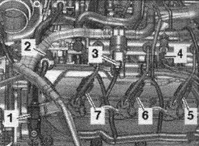
For reinstallation, mark the correspondence of the high pressure lines to the injectors. Loosen the union nuts of the high-pressure lines "1...6" using a 17 mm socket "VAG 1331/6" and heads "T40055" and remove the high-pressure lines.
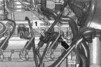
Remove the return fuel pipes. fuel lines from the injection nozzles; to do this, pull the unlocking bolt upwards "arrow". Remove the pressure relief valve "1" from the bracket and set the valve aside with the connected fuel lines. hoses to the side.
The following illustrations show the left cylinder head cover. Unscrew the injector cover bolts "arrows". Pull the lids up and turn them 90°.
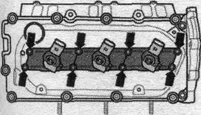
Unscrew the injector "arrow" bolts.
Previously used injectors should only be installed on the same cylinder. Mark the correspondence of each injector to the cylinder. Remove the injection nozzles using the "T10055" puller with the "T10055/1" adapter.
Loosen the cylinder head cover bolts "arrows" crosswise. Unscrew the bolts and remove the cylinder head cover.
Install
Installation in reverse order. Replace the damaged cylinder head cover gasket. Replace the cylinder head cover bolts with a damaged gasket. Hose fittings, air tubes and hoses must be cleaned of oil and grease before installation. To secure all hose connections, use clamps of the appropriate series. Clean the seating surfaces; there should be no oil or grease on them. Tighten the cylinder head cover bolts crosswise in several steps. Install injectors, high pressure lines, air housing. filter and pressure sensor 1 of the exhaust gas "G450". Check the fuel. system for leaks.