
Attachment drive chain
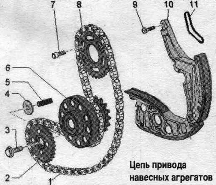
1. Power take-off drive chain.
2. Oil chain drive sprocket. pump; mounting position: the side with the inscription faces the engine.
3. Bolt.
4. Crankshaft axial fixing insert.
5. Pressure spring.
6. Crankshaft.
7. Bolt: 23 Nm.
8. Balance shaft sprocket; mounting position: the side with the inscription faces the gearbox.
9. Bolt: 9 Nm.
10. Chain tensioner: with a guide bar.
11. Gasket: replace.
Removal and installation the auxiliary chain. units
The gearbox is removed. Remove the driven disk. Remove the timing chain protective covers.
Risk of damage to the drive chain due to threads that are too long. Only bolts with a thread length "a" of maximum 22 mm may be used to lock the wrench "T40049". If only bolts with a longer thread are available, place a washer under the bolt head to ensure a thread length of 22 mm.
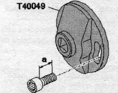
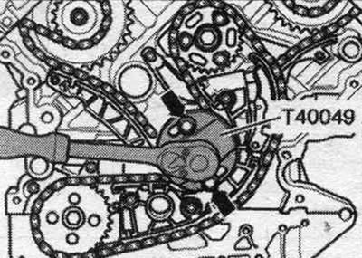
Install the "T40049" key onto the rear of the crankshaft using 2 "arrow" bolts.
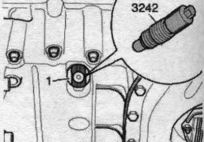
Unscrew the threaded plug "arrow" of the upper part of the oil. pallet, use a socket wrench with a ball head for this.
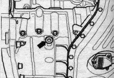
Screw the fixing bolt "3242" into the hole with a torque of 20 Nm, if necessary, slightly turn the crankshaft in both directions to fully center the bolt.
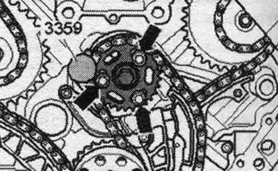
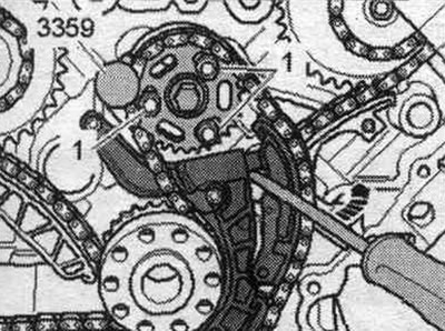
Risk of damage to previously used chain add. drive when changing its stroke. For reassembly, mark the direction of the auxiliary chain with an arrow. units, use paint for this. Secure the balance shaft behind the engine using the locking pin for the high-pressure fuel pump "3359" and unscrew the bolts of the balance shaft chain sprocket "arrows".
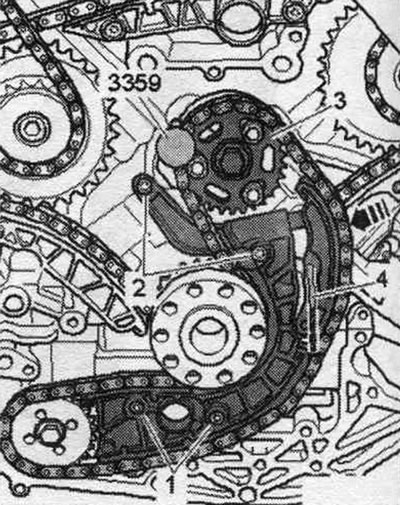
For protection against cuts, wrap the cutting edges of the 3.3 mm diameter drill with insulating tape. Press the chain tensioner rail in the "direction of the arrow" and lock the chain tensioner with the 3.3 mm diameter drill "pos. 4". Unscrew the bolts "1" and "2" and remove the chain tensioner, balance shaft sprocket "3" and chain.
Install
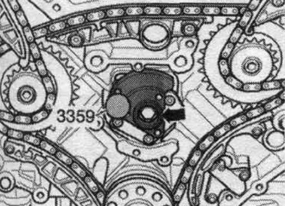
Crankshaft "1" is locked in the "TDC" position using locking screw "3242." Secure the balance shaft "arrow" at the rear of the engine using fuel injection pump locking pin "3359.".
Install the chain tensioner with the chain and the balance shaft chain sprocket. The holes in the chain sprocket "3" must be in the middle position in relation to the threaded holes of the balance shaft. Tighten bolts "1" and "2" of the chain tensioner. "Pos. 4" and "arrow" should not be taken into account. Screw in the sprocket arrow bolts without tightening. The sprocket should rotate on the balance shaft, but should not tilt to the sides. Remove the drill from the hole, this will release the chain tensioner. Press the screwdriver in the direction of the arrow against the tensioner damper and simultaneously tighten the bolts "1" of the chain sprocket. Remove the locking pin for the high-pressure fuel pump "3359" from the balance shaft.
Installation in reverse order. Install the timing chain protective covers. Install the driven disk. Fill with oil and check its level.
Balance shaft
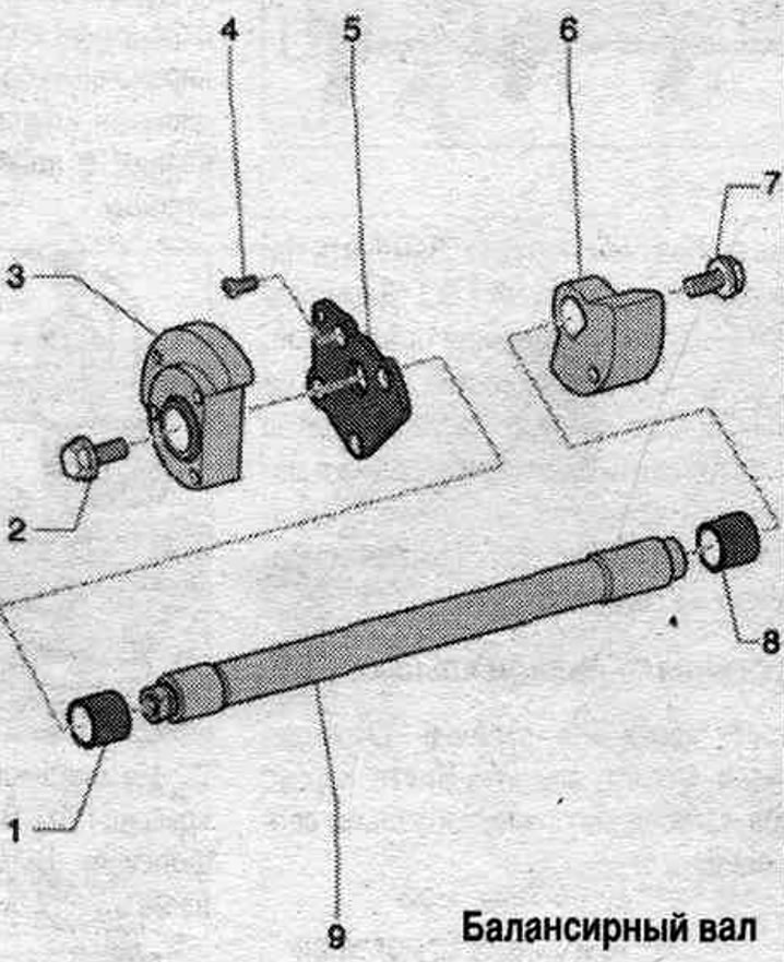
1. Plain bearing.
2. Bolt: 60 Nm; when loosening and tightening, use the "3359" fuel pump locking tool as a counter-key.
3. Counterweight from the CP side.
4. Bolt: insert with threaded varnish; 9 Nm.
5. Support body.
6. Balance beam on the belt pulley side.
7. Bolt: 60 Nm; when loosening and tightening, use the "3359" fuel pump locking tool as a counter-key.
8. Plain bearing.
9. Balance shaft.