
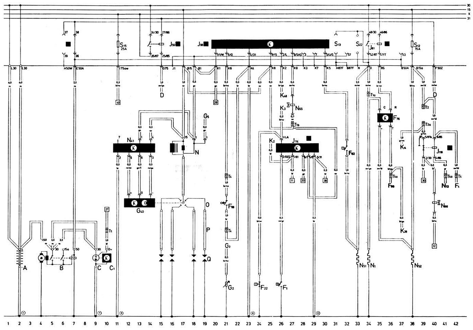
Features of the electrical circuit of cars AUDI "100" with the engine "DS"
| Designation | Name | Position |
| A | Battery | 2 |
| IN | Starter | 4-7 |
| WITH | Generator | 9 |
| C1 | Voltage regulator | 10 |
| D | Ignition switch | 15, 40 |
| F1 | Oil pressure sensor calibrated at 1.8 kg/cm² | 26 |
| F22 | Oil pressure sensor calibrated to 0.3 kg/cm² | 24 |
| F4 | Reverse light switch | 42 |
| F62 | Vacuum switch for gear shift indicator | 32 |
| F66 | Low Coolant Level Indicator Sensor | 36 |
| F68 | Gear shift indicator sensor | 21 |
| F76 | Electronic thermal switch | 35, 36 |
| G2 | Coolant Temperature Gauge Sensor | 21 |
| G3 | Coolant temperature gauge | 21 |
| G5 | Tachometer | 19 |
| G40 | Hall sensor of the ignition distributor sensor | 12-14 |
| J59 | Unloading relay of contact "X" of the outdoor lighting switch | 14-15 |
| J81 | Intake manifold heating relay | 34, 35 |
| J98 | Gear shift indicator and forced idle control unit | 20-30 |
| J114 | Oil Pressure Warning Light Control Unit | 26-29 |
| J118 | Brake lining wear indicator lamp switch relay | 39, 40 |
| K2 | Low battery indicator light | 25 |
| KZ | Oil pressure warning light | 26 |
| K14 | Parking brake and brake lining wear indicator light | 37 |
| K28 | Coolant temperature warning light | 37 |
| K48 | Gear Shift Indicator Light | 26 |
| N | Ignition coil | 16-19 |
| 2 | Heating element of the automatic starting device of the carburetor | 34 |
| N13 | Brake lining wear sensor for left wheels (circuit breaker) | 41 |
| N41 | Ignition system switch | 11-14 |
| N51 | Intake manifold heating resistor | 33 |
| N52 | Heating element of the carburetor partial load system channel | 38 |
| N65 | Solenoid shut-off valve | 27 |
| N69 | Thermal relay of forced idle running time | 40 |
| O | Ignition distributor sensor | 15-19 |
| R | Candle tips | 15-19 |
| Q | Spark plugs | 15-19 |
| S12, S15 | Fuses on the mounting block | |
| T1 | Single plug connector (on the right in the powertrain compartment) | |
| T1a | Single plug connector (behind the instrument cluster) | |
| T1b | Single plug connector (behind the instrument cluster) | |
| T2 | 2-Plug Connector (behind the instrument cluster) | |
| T2a | 2-Plug Connector (behind the instrument cluster) | |
| T4 | 4-pin connector (on the right 8 compartment of the power unit) | |
| T4a | 4-pin connector (green, behind the instrument cluster) | |
| Ground connection points | ||
| 1 | Ground jumper between battery and body | |
| 7 | Jumper to ground between generator and engine | |
| 8 | Ground connection point behind the instrument cluster | |
| Relay placement | ||
| [3] | Gear shift indicator control unit on the mounting block | |
| [5] | Unloading relay of contact "X" of the external lighting switch on the mounting block | |
| [10] | Relay for switching on the intake manifold heating on the mounting block | |
| [1] | Brake lining wear indicator lamp relay on the relay block | |
| [6] | Oil pressure warning light control unit on relay block |
(The text is based on materials from the website «audimanual.ru»)