



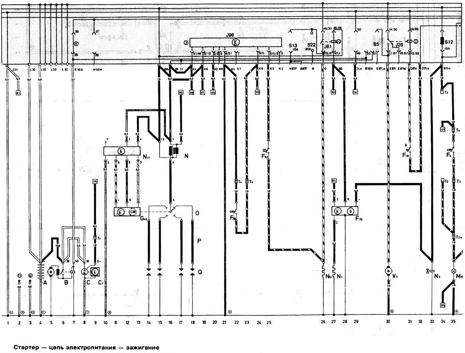
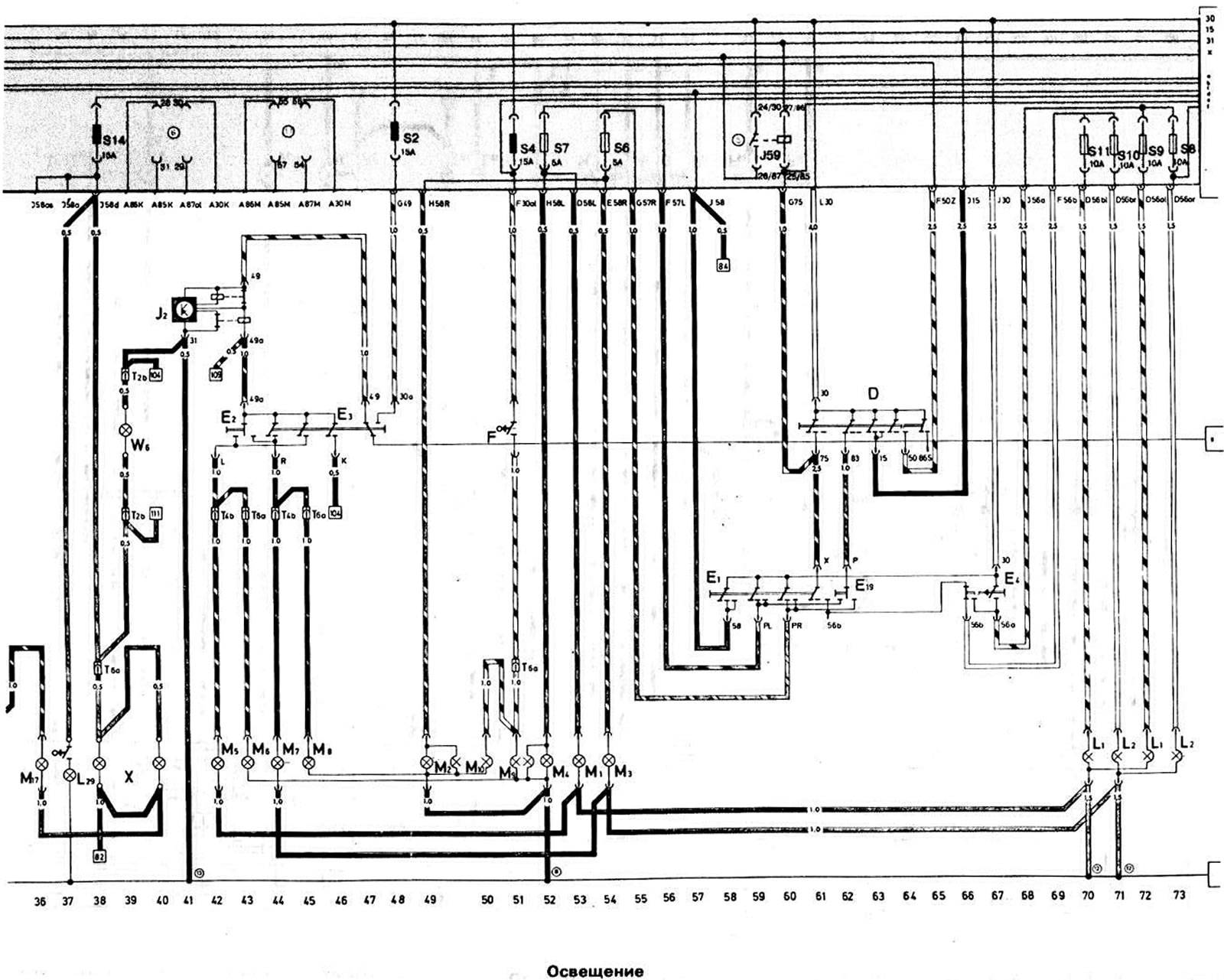
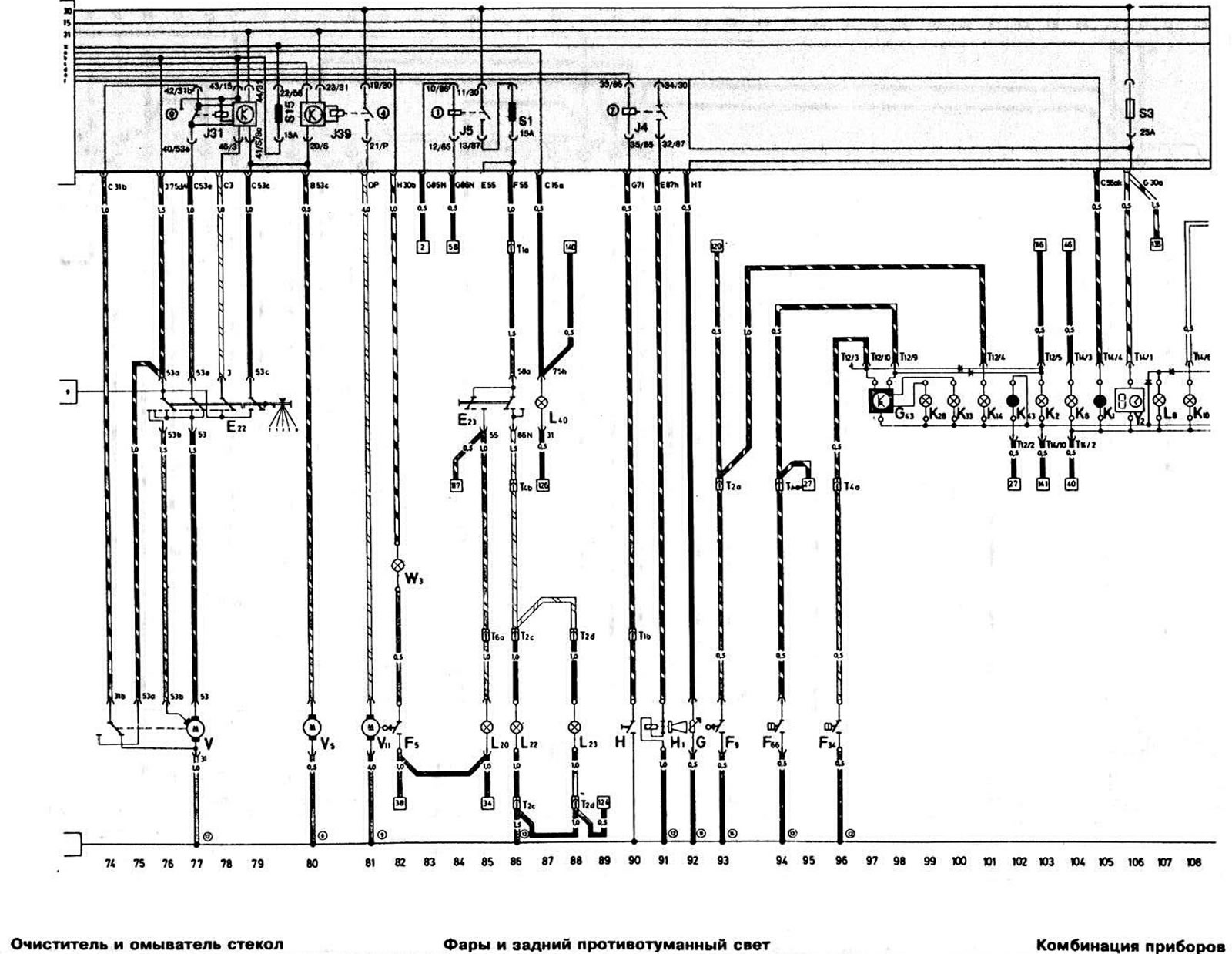
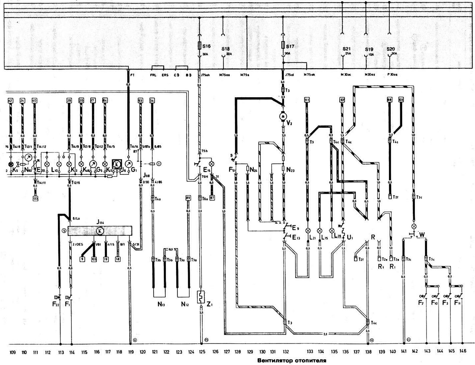
Wiring diagram of AUDI "100" cars with "DR" engine 1983
| Designation | Name | Position |
| A | Battery | 4 |
| 8 | Starter | 5-7 |
| WITH | Generator | 8 |
| C1 | Voltage regulator | 9 |
| D | ignition switch | 61-64 |
| E1 | Outdoor Light Switch | 58-61 |
| E2 | Turn signal switch | 43 |
| EZ | hazard warning switch | 44-47 |
| E4 | Headlight switch | 66-67 |
| E9 | Air flow and heater fan switch (upper handle on the heater control panel) | 132 |
| E13 | Air distribution switch (lower handle on the control panel from the axis of the roofing felt) | 132 |
| E15 | Rear Window Defogger Switch | 125, 126 |
| E19 | Side light switch | 62 |
| E20 | instrument lighting switch | 111 |
| E22 | Windscreen wiper switch | 76-79 |
| E23 | Fog light and rear fog light switch | 85,86 |
| F | Brake light switch | 51 |
| F1 | Oil pressure sensor calibrated at 1.8 kg/cm² | 114 |
| F2 | ceiling light switch in the left front door pillar | 143 |
| F3 | Ceiling light switch in the right front door pillar | 145 |
| F4 | reverse light switch | 35 |
| F5 | trunk light switch | 82 |
| F9 | parking brake warning light switch | 93 |
| F10 | ceiling light switch in the left rear door pillar | 144 |
| F11 | ceiling light switch in the right rear door pillar | 146 |
| F18 | Engine cooling system fan motor switch sensor | 31 |
| F22 | Oil pressure sensor calibrated to 0.3 kg/cm² | 113 |
| F34 | BRAKE FLUID LEVEL WARNING LAMP SWITCH | 96 |
| F51 | Overheating fuse (on the holder) | 128 |
| F62 | Vacuum switch for gear shift indicator | 25 |
| F66 | Low Coolant Level Indicator Sensor | 94 |
| F68 | Gear shift indicator sensor | 22 |
| F76 | Electronic thermal switch | 27-29 |
| G | Fuel level sensor | 92 |
| G1 | Fuel level indicator | 119 |
| G5 | Tachometer | 116 |
| G40 | Hall sensor of the ignition distributor sensor | 11-13 |
| G43 | Electronic control circuit for coolant temperature and brake fluid level warning lights | 98 |
| N | Horn switch | 90 |
| H1 | Sound signal | 91 |
| J2 | Direction indicator and hazard warning flasher relay | 41-43 |
| J4 | Horn Relay® | 90, 91 |
| J5 | Fog Light Switch Relay® | 84, 85 |
| J6 | Voltage stabilizer | 118 |
| J26 | Engine cooling system fan motor switch relay | 30-32 |
| J31 | Windscreen Wiper Intermittent Relay® | 77-79 |
| J39 | Headlight Washer Relay® | 80, 81 |
| J59 | Unloading relay contact "X" (outdoor lighting switch)® | 59 |
| J81 | Intake manifold heating relay® | 26, 27 |
| J98 | Gear Shift Indicator Control Unit ® | 18-25 |
| J114 | Oil Pressure Warning Light Control Unit® | 114-119 |
| J118 | Brake Pad Wear Indicator Lamp Switch Relay® | 120,121 |
| K1 | High beam indicator lamp | 105 |
| K2 | Low battery indicator light | 103 |
| KZ | Oil pressure warning light | 114 |
| K5 | Direction indicator lamp | 109 |
| Kb | Hazard warning light indicator | 104 |
| K10 | Rear window heating indicator light | 108 |
| K13 | Rear fog light indicator lamp | 117 |
| K14 | Parking brake and brake lining wear indicator light | 101 |
| K28 | Coolant temperature warning light | 99 |
| KZZ | Brake fluid level warning light | 100 |
| K43 | Low Coolant Temperature Warning Light | 102 |
| K48 | Indicator light of the on-gear indicator | 115 |
| L1 | Low and high beam lamp of the left headlight z | 70,72 |
| L2 | Right headlight low and high beam lamp | 71,73 |
| L8 | Clock Lighting Lamp | 107 |
| L10 | Instrument cluster illumination lamp | 112,113 |
| L15 | Ashtray Lighting Lamp | 134 |
| L20 | Rear fog light bulb | 85 |
| L21 | Heater lever illumination lamp | 133 |
| L22 | Left fog light bulb | 86 |
| L23 | Right fog light bulb | 88 |
| L28 | Cigarette lighter socket illumination lamp | 135 |
| L29 | Underhood lamp | 37 |
| L40 | Headlight and rear fog light switch illumination lamp | 87 |
| MG | Parking light bulb in the left headlight | 53 |
| N12 | Parking light bulb in left rear light | 49 |
| M3 | Parking light bulb in the right headlight | 54 |
| M4 | Parking light bulb in the right rear light | 52 |
| M5 | Left Front Turn Signal Lamp | 42 |
| Mb | Turn signal lamp in left rear light | 43 |
| M7 | Right Front Turn Signal Lamp | 44 |
| M8 | Direction indicator lamp in the right rear light | 45 |
| M9 | Brake light and side light bulb in left rear light | 51 |
| M10 | Brake light and side light bulb in right rear light | 50 |
| M16 | Reversing light bulb in left rear light | 35 |
| M17 | Reversing light bulb in the right rear light | 36 |
| N | Ignition coil | 16, 17 |
| N1 | Heating element of the automatic starting device of the carburetor | 27 |
| N3 | Warm air shut-off valve | 33 |
| N12 | Right brake pad wear sensor | 123,124 |
| N13 | Left brake pad wear sensor | 121.122 |
| N₂3 | Additional resistor for the heater fan motor | 132 |
| N₂4 | Additional resistor for the heater fan motor | 129 |
| N41 | Ignition system switch | 10-13 |
| N51 | Intake manifold heating resistor | 26 |
| N60 | Solenoid valve of the economizer | 110 |
| ABOUT | Ignition distributor sensor | 14-18 |
| R | Spark plug tips | 14-18 |
| ABOUT | Spark plugs | 14-18 |
| R | Radio receiver connector | 138, 139 |
| R1 | Antenna connector | 139, 140 |
| S1, S3, S15-S21 | Fuses on the mounting block | |
| S2, S4, S6-S12, S14 | Fuses on the mounting block | |
| T1 | Single-plug connector (in the powertrain compartment) | |
| T1a | Single plug connector (behind the instrument cluster) | |
| T1b | Single plug connector (behind the instrument cluster) | |
| T2 | 2-Plug Connector (behind the instrument cluster) | |
| T2a | 2-Plug Connector (behind the instrument cluster) | |
| T2b | 2-Plug Connector (behind the instrument cluster) | |
| T2s | 2-Plug Connector (in the powertrain compartment on the left) | |
| T2d | 2-Plug Connector (in the powertrain compartment on the right) | |
| T2e | 2-Plug Connector (behind the instrument cluster) | |
| T2r | 2-Pin Body Position Regulator Connector (behind the instrument cluster) | |
| TZ | 3-pin connector (behind the instrument cluster) | |
| TZa | 3-pin connector (in the powertrain compartment on the right) | |
| T3b | 3-pin connector (in the powertrain compartment on the left) | |
| TZs | 4-pin connector (behind the instrument cluster) | |
| T4 | 4-pin connector (in the powertrain compartment on the left) | |
| T4a | 4-pin connector (behind the instrument cluster) | |
| T4b | 4-pin connector (behind the instrument cluster) | |
| T4s | 4-pin connector (behind the instrument cluster) | |
| Tba | 6-pin connector (behind the instrument cluster) | |
| T12 | 12-pin instrument cluster connector | |
| T14 | 14-pin instrument cluster connector | |
| U1 | Cigarette lighter | 136 |
| V | Windscreen wiper motor | 74-77 |
| V2 | Heater Fan Motor | 132 |
| V5 | Windscreen washer motor | 80 |
| V7 | Electric fan of the engine cooling system | 39 |
| V11 | Headlight washer motor | 81 |
| W | Interior light | 142 |
| W3 | Trunk light lamp | 82 |
| W6 | Glove compartment light | 38,40 |
| X | License plate light | |
| Y2 | Digital display watch | 106 |
| Z1 | Rear window heating element | 125 |
| 1 | Jumper to ground "battery - body" | |
| 7 | Jumper to ground "engine - generator" | |
| 8 | Ground connection point behind the instrument cluster | |
| 9 | Ground connection point in the powertrain compartment on the left | |
| 11 | Ground connection point in the trunk | |
| 12 | Ground connection point by soldering in the instrument cluster wire harness | |
| 13 | Ground connection point for soldering in the instrument cluster wire harness | |
| 14 | Ground connection point at the parking brake actuator lever | |
| 15 | Ground connection point under the rear shelf |
This publication is borrowed from the resource AudiManual.ru