
Leave the repair of the shock absorber strut to the workshop. For your information, we provide pictures showing the fastening of the shock absorber strut. Depending on the design of the chassis, there may be slight differences. In any case, before disposing of faulty shock absorbers, it is necessary to remove gas and oil from them.
1. Remove the wheel.
2. Before dismantling the shock absorber strut, detach the tie rods for automatic headlight leveling from the suspension support arm by opening the metal clamp.
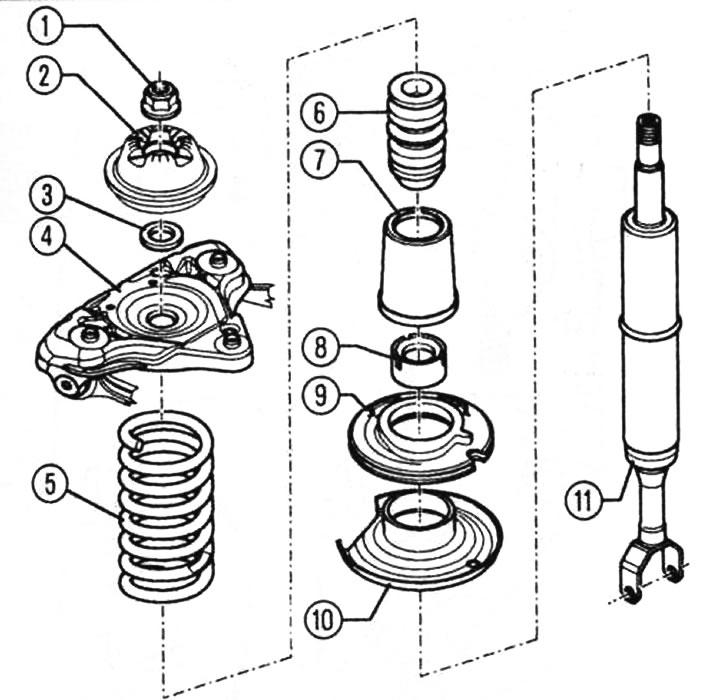
Shock absorber strut mounting: 1 - flange nut 60 Nm(must be replaced), 2 - bearing, 3 - washer, 4 - bearing bracket, S - helical spring, 6 - additional spring, 7 - protective shell, 8 - cap, 9 - lower support, 10 - lower spring plate, 11 - shock absorber.
3. Remove the brake caliper and attach it to the body. Use the wheel mounting bolt to secure the brake disc.
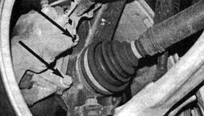
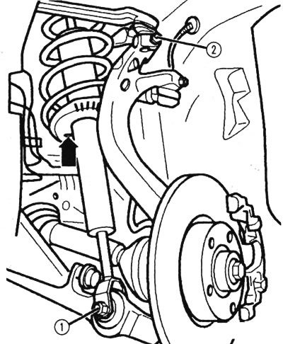
To remove the brake caliper, you only need to unscrew two screws (arrows)
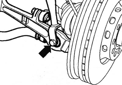
4. Remove clamp 1 with pliers; do not insert it during installation. Loosen nut 2. Then remove the hex bolt and pull both wheel suspension arms upwards. Caution! Do not widen the groove in the bearing housing with a chisel or similar tools.
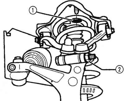
To remove the shock absorber strut, remove clamp 1 and loosen nut 2
5. Protect the steering gear bellows from damage. Cut a strip A 20...25 mm wide from protective shell 1.
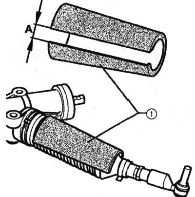
The open (with the slot) part of the shell 1 should be directed downwards
6. To avoid damaging the lower wishbone joints of the independent wheel suspension, protect the engine and gearbox from excessive spring return travel.
7. After removing the hex bolt (arrow) from the shock absorber strut and support arm, the wheel bearing housing can be unscrewed.
Unscrew the shock absorber strut and suspension support arm (arrow) and hang the wheel bearing housing to the side
8. Loosen the coolant expansion tank and remove the battery compartment cover. To do this, remove the cover (arrow) under which the screw is located.
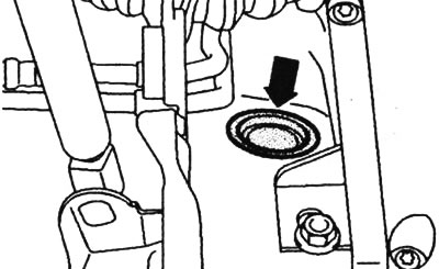
After removing the battery compartment cover, remove the screw cover
9. Before removing the shock absorber strut together with the bearing bracket, unscrew the screws 1 in the battery section. Do not damage the protective shell of the hinge!
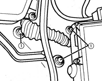
The shock absorber can be removed after removing the screws in the battery section
10. When installing, insert the shock absorber strut itself and the bearing bracket into the dome. Before tightening the hexagon head screws 1 in the battery section, pay attention to the correct seating of the washers.
11. Rubber-metal bearings 2, 3, 4 and 5 have a limited torsional stress resistance. Therefore, tighten the bolt connections on the independent wheel suspension arms only when the vehicle is on the ground. After inserting the fork-shaped head of the strut into the suspension arm, tighten bolt 1 to 90 N·m. The bolt is inserted against the direction of travel.
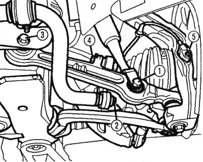
Rubber-to-metal bearings and fork-shaped head of the shock absorber strut
12. Reinstall both upper suspension arms. Tighten nut 2 to 40 Nm. When tightening, push the upper arms down as far as possible.
13. Insert the anti-lock braking system wire into the holder on the brake caliper, screw on the caliper and tighten it to a torque of 190 Nm.
When tightening the nut, push both upper suspension arms down as far as possible
This publication is borrowed from the resource: AudiManual.ru