
Table of contents: Removal ↓ Installation ↓
Removal
1. For this operation, select a level, firm area with sufficient space to work.
2. Apply the handbrake, chock the rear wheels, jack up the front of the car and install safety stands. Remove the front wheels.
3. Remove the power unit protective cover and sound insulation.
4. Disconnect the ground cable from the battery and move it away from the terminal as described in chapter 5A.
5. If necessary, loosen the nuts and remove the top engine cover.
6. Remove the exhaust pipe as described in chapter 4B, being careful not to bend the excessively flexible section. If necessary, remove the bracket securing the inlet pipe from the gearbox.
7. Disconnect the wiring from the speedometer sensor.
8. Label the wiring connectors at the rear of the transmission and disconnect them. Disconnect the wiring bracket and move the wiring to the side.
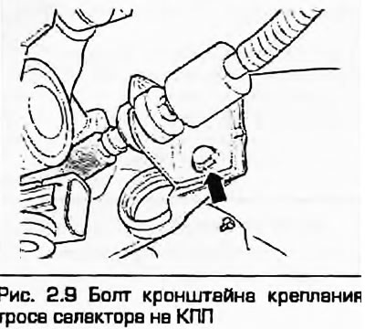
9. Set the selector to the "P" position, carefully disconnect the cable end from the lever and remove the support bracket (Fig. 2.9). Move the cable to the side.
10. Using a hex key, unscrew the bolts securing the heat shields above the inner joint of the right drive shaft.
11. As described in Chapter 8, disconnect the drive shafts from the gearbox. Move them to the side and tie them up so they don't get in the way.
12. Remove the right gearbox support together with the screen.
13. Place a suitable container under the gearbox to collect the transmission fluid.
14. Disconnect the hydraulic pipes from the gearbox, remove the sealing rings. On petrol models without air conditioning, unscrew the bolts and remove the pipes. On all other models, unscrew the connecting nuts, which are located at the bottom left of the radiator and also the nuts, which are located at the bottom in front of the gearbox. Remove the pipes completely. Plug the holes in the gearbox housing to prevent dirt from getting in.
15. Remove the starter - see Chapter 5A.
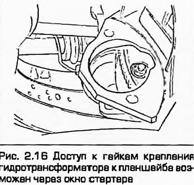
16. Turn the engine until one of the nuts securing the torque converter to the faceplate appears in the starter window (Fig. 2.16). Unscrew the nut, holding the engine from turning with a screwdriver inserted between the teeth of the ring gear and the bell. Unscrew the remaining two nuts, turning the engine a third of a turn each time.
17. Unscrew the bolts securing the automatic transmission to the engine, accessible from under the hood.
18. Support the engine weight on a hoist or beam placed in the front fender grooves. If necessary, remove the hood to do this, as described in chapter 11. Automatic transmission is a heavy unit and the engine must be suspended by both eyes. Depending on the engine model, remove the components required for this operation.
19. Support the automatic transmission with a trolley jack or stand.
20. On turbocharged petrol engines, mark the position of the subframe relative to the body and loosen the front subframe mounting bolts. Remove the remaining subframe bolts and lower the rear of the subframe.
Note: It is very important to install the subframe in the correct place during assembly so that it does not affect the handling of the car and does not lead to premature wear.
21. Unscrew the bolts securing the automatic transmission to the engine, accessible from below.
22. With the help of an assistant, remove the automatic transmission from the guide bushings on the engine, making sure that the torque converter remains on the input shaft. If necessary, pry the torque converter off the faceplate.
23. After removing the automatic transmission from the guide bushings, lower it down on the jack. Tie a wire or metal strip across the bell housing to prevent the torque converter from slipping off the shaft.
Warning: Ensure the stability of the automatic transmission on the jack, do not allow it to slip off the automatic transmission shaft or torque converter.
24. If necessary, remove the intermediate plate from the guide bushings.
Installation
25. Installation is the reverse procedure. Please note the following:
- a) If necessary, install a torque converter in the gearbox. Make sure that the protrusions on the torque converter hub are aligned with the cutouts in the inner wheel of the hydraulic pump.
- b) Tighten all threaded connections to the specified torques. Always replace self-locking nuts and bolts.
- c) Replace the O-rings of the hydraulic tubes and the filler tube on the automatic transmission housing.
- d) Tighten the automatic transmission mounting bolts to the specified torques.
- d) Check the fluid levels in the final drive and automatic transmission as described in the chapter 1A or 1B.
- e) Finally, check the selector cable adjustment as described in paragraph 4.
The original version is on the portal Audimanual.ru