
Table of contents: Dismantling the ignition switch… ↓ Ignition switch failure ↓
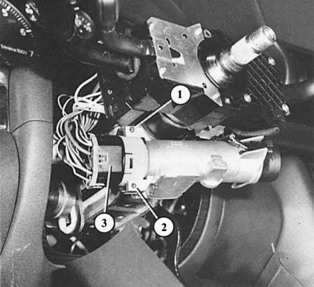
With the steering column trim removed, both countersunk screws (1 and 2) are visible, which secure the ignition switch assembly to the lock. The number "3" shows the connector connected to the switch assembly.
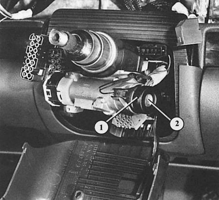
The ignition switch (2) is equipped with a receiver (1) for the ignition switch transponder, which, if necessary, activates the vehicle's drive-away lock.
In this section we will consider the electrical unit of the ignition switch. But the repair of the lock mechanism should be performed by a workshop.
Dismantling the ignition switch assembly
1. Remove the steering column trim at the top and bottom as described in section Switches.
2. Remove the varnish on the seal and loosen the two small countersunk screws at the top and bottom of the ignition switch assembly bracket.
3. Remove the switch assembly downwards.
4. When installing the new switch assembly, ensure that the lock control pin fits into the recess on the switch assembly.
5. Screw in the countersunk screws and secure them with a drop of varnish.
Ignition switch failure
This description will not make you a car thief, but it will significantly help you continue your trip if the ignition switch is defective. Despite this, the ignition key must be there, at least because of the presence of the vehicle's departure blocking transponder. Of course, it must also turn in the lock so that the steering wheel lock can be released. If the steering lock itself is defective, you should not continue your trip, otherwise the steering wheel lock may work while driving.
1. Remove the receiving pocket on the left under the instrument panel (chapter Salon).
2. Disconnect the multi-pin connector on the ignition switch. The wire connectors that should short are now exposed.
3. Now connect, for example, with a paper clip, the contacts of one of the two thick red wires to the contact of the black wire. Thanks to this, the ignition turns on.
4. To start the engine, make yourself an insulated second jumper from a wire, which is first connected to the red/black wire.
5. Apply the second jumper to the existing jumper for a moment, and remove it immediately as soon as the starter starts the engine.
6. It is better to remove the second jumper completely, and insulate the first one well so that it cannot touch the exposed parts. Otherwise, a powerful short circuit will occur, since the red wires do not have a fuse.
7. To turn off the engine, remove the jumper between the red and black wires.