
Note: If the engine is in the vehicle, first do the following:
- (a) Disconnect the negative battery cable
- (b) Remove the air filter and fuel injection system components (Section 3)
- (c) Disconnect all related electrical wiring, cables and hoses
- (d) Remove the distributor (Section 4)
- (e) Remove the upper fan shroud and the upper intake manifold
- (J) Disconnect the drive belts from the crankshaft pulley
- (g) Where used, remove the power steering pump leaving the hoses connected (Section 10)
- (h) Where used, remove the air conditioning compressor leaving the hoses (Section 11)
1. Unscrew the nuts/bolts, lift the valve cover. Remove the reinforcement strips (where are they used) and gaskets. Note the location of the cable holders.
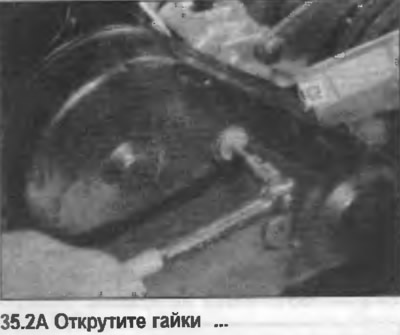
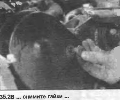
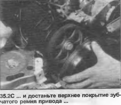
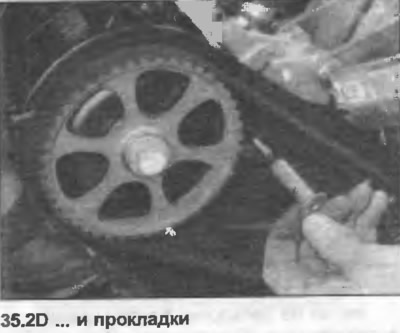
2. Unscrew the nuts, remove the upper cover of the toothed belt drive and the gaskets (photo). The lower cover should not be removed.
3. Turn the engine so that the piston of cylinder No.1 is at TDC (top dead center) during the compression stroke.
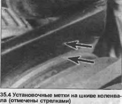
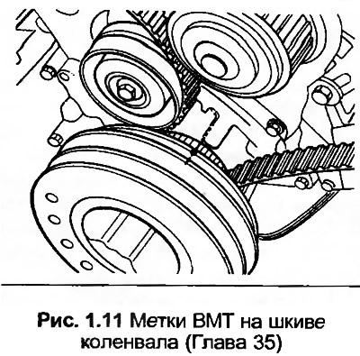
4. The notch in the crankshaft pulley should be aligned with the pointer on the oil pump housing or lower drive cover (photo). Alternatively, the "0" (TDC) mark on the flywheel/drive plate should be aligned with the pointer in the clutch housing bore.
5. The valves of cylinder No.1 must be closed, the cam lobe projections turned upward.
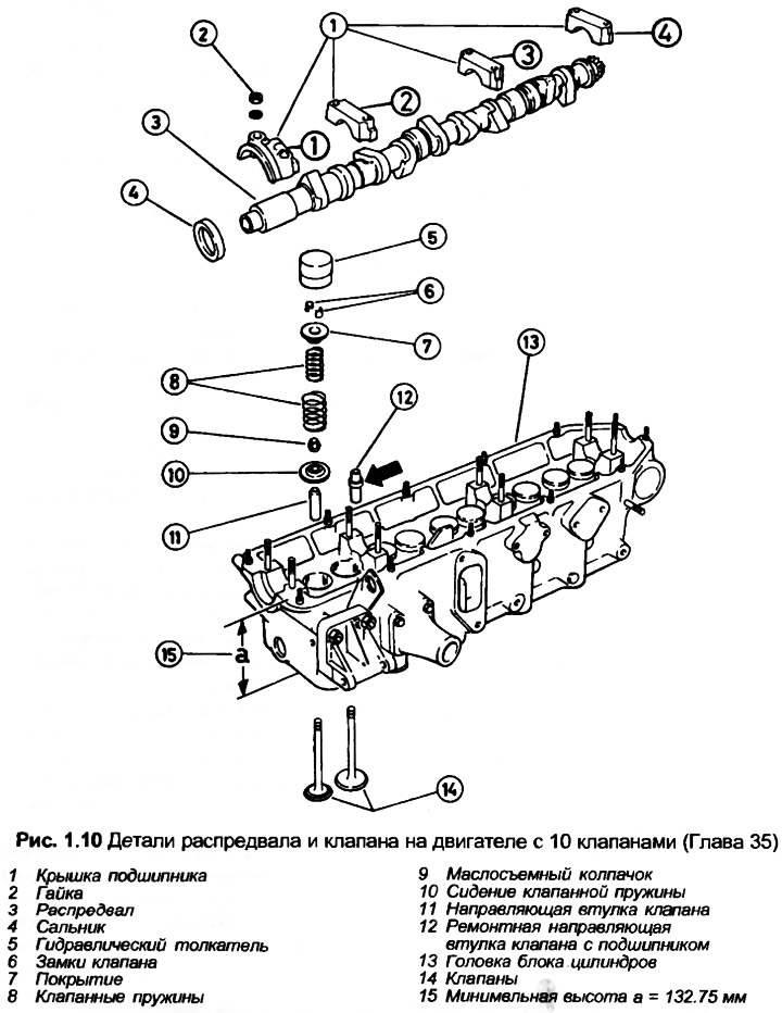
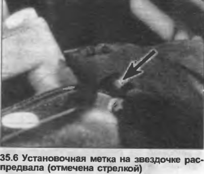
6. On 10-valve engines, the recess on the rear of the camshaft gear must be aligned with the top surface of the valve cover gasket (photo), (temporarily install a gasket if necessary).
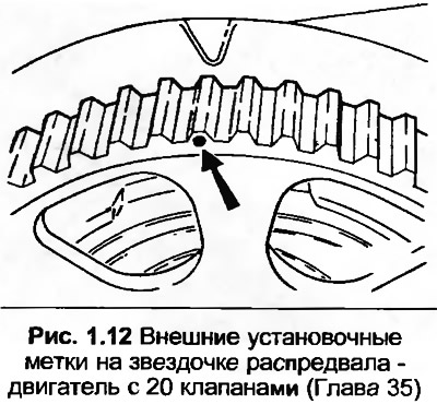
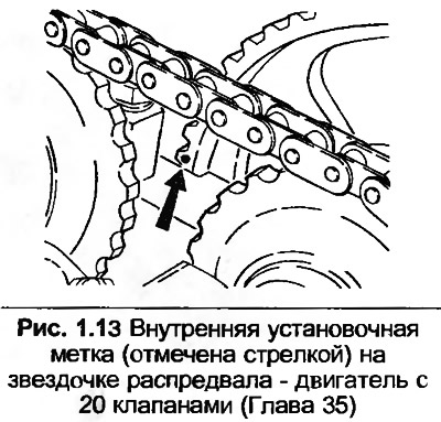
7. On 20-valve engines, the recess at the rear of the camshaft sprocket should be aligned with the top edge of the cylinder head between the camshafts. Alternatively, the recess at the front of the sprocket should be aligned with the mark on the valve cover (temporarily installed).
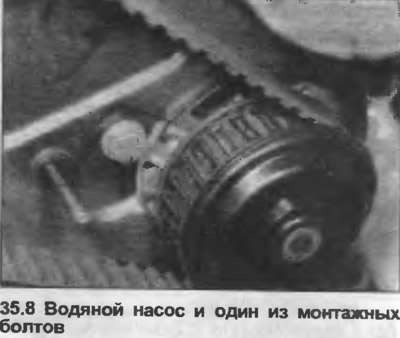
8. Loosen the water pump mounting and adjustment bolts, turn the pump clockwise to reduce the tension of the toothed drive belt (photo).
9. Remove the toothed drive belt from the camshaft sprocket and move it to one side.
10. Remove the center bolt from the camshaft sprocket, locking it using the method shown in photo 25.53 (Part A).
11. Remove the sprocket from the camshaft and remove the woodruff key.
12. Check that each bearing cap is numbered; if not, make a mark on the lid. Note that the lids are slightly offset and can only be installed in one direction.
13. It is important to follow the description exactly when removing the camshaft so that there is no risk of distortion.
10 valve engines
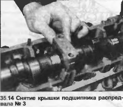
14. Unscrew the nuts of bearing caps No.1 and 3 and remove them (photo).
15. Evenly and in a diagonal sequence, unscrew the nuts of the bearing caps No.2 and 4, then remove them.
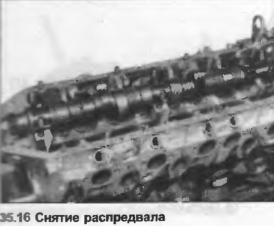
16. Lift the camshaft and remove the oil seal (photo).
20 valve engine
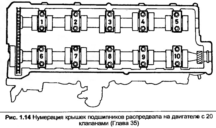
17. Unscrew nuts of covers No.2 and 4 of the exhaust camshaft bearings (Fig. 1.14) and remove them.
18. Evenly and in a diagonal sequence, unscrew the nuts of bearing caps No.1, 3 and 5, then remove the caps.
19. Lift the exhaust camshaft and disconnect it from the chain.
20. Unscrew nuts No.7 and 9 of the intake camshaft bearing caps (Fig. 1.14) and remove them.
21. Evenly and in a diagonal sequence, unscrew the nuts of the bearing caps No.6, 8 and 10, then remove the caps.
22. Raise the intake camshaft, remove the chain.
All engines
23. Prepare a box with marked internal compartments to store the pushers.
24. Remove the hydraulic lifters and place them upside down in the box to prevent oil from leaking out.
[The original article is posted on the resource: audimanual.ru]