



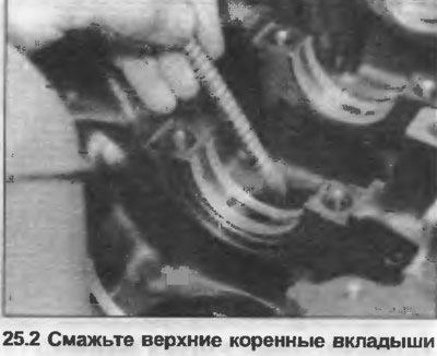
2. Position the upper main bearing shells in the crankcase so that the tabs fit into the recesses. Lubricate the bearing shells (photo). If using old shells, make sure they are installed in their original positions.
3. Lower the crankshaft into the crankcase.
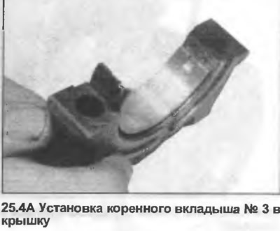
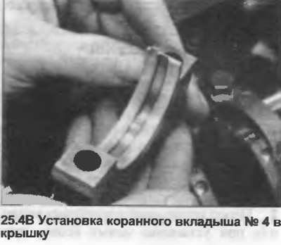
4. Place the lower main bearing shells in the caps; for caps #1, 2 and 5 they are solid, and for cap #4 the shells have a lubrication groove. Bearing shell #3 is also solid, but the repair one contains a thrust flange (photo).
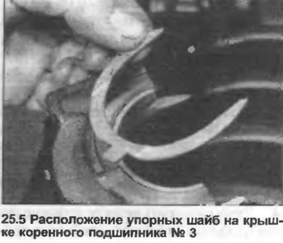
5. Place thrust washers on each side of cover #3, using grease to secure them in place (photo). Make sure the oil grooves are facing out.
6. Lubricate the bearing shell, then install the main bearing cap No.3, insert the bolts and tighten them to the tightening torque specified in the Specification.
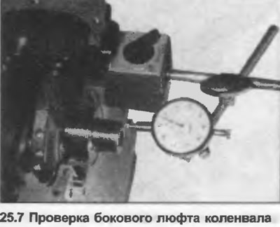
7. Using the feeler gauge (photo 9.60) or micrometer, check that the lateral clearance corresponds to the data in the Specifications (photo).
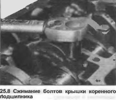
8. Lubricate the remaining main bearing shells, then install the caps, insert the bolts and tighten them to the tightening torque specified in the Specification (photo).
9. Check that the crankshaft rotates freely.
10. Place the block on its side, turn the crankshaft so that the journal of connecting rod No.1 is at BDC.
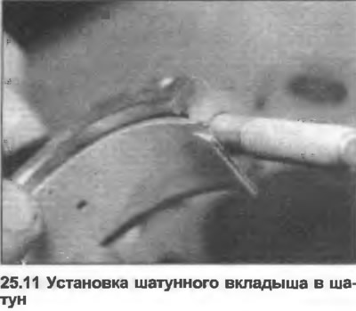
11. Position the bearing shell in the connecting rod so that the protrusion fits into the recess (photo). Lubricate the bearing shell.
12. Position the piston ring cuts 120° apart. Generously lubricate the rings and grooves, install the piston ring puller on the piston.
13. Lubricate the cylinder bore, then insert the piston and connecting rod, with the arrow on the piston head facing the front end of the engine.
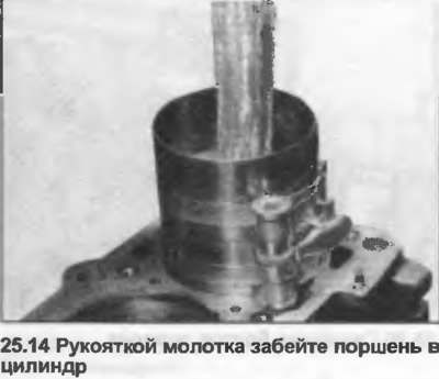
14. Using the hammer handle, gently drive the piston through the compressor into the cylinder bore, directing the connecting rod onto the crankshaft journal (photo).
15. Position the connecting rod bearing shell into the connecting rod cap. Lubricate the bearing shell.
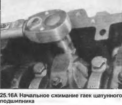
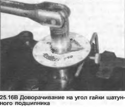
16. Install the lower connecting rod cap with the bearing shell onto the stands, then lubricate the contact surfaces and install the nuts. Tighten the nuts first to the tightening torque specified in the Specification, then turn them through an angle of 90° (photo). Make sure that the cap is correctly oriented.
17. Repeat the procedure given in steps 10-16 for the remaining piston and connecting rod assemblies.
18. Temporarily insert two bolts into the rear of the crankshaft, use a rod to turn the engine to check if the crankshaft rotates easily.
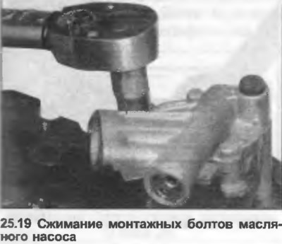
19. Install the oil pump into the block, insert the mounting bolts and tighten them to the tightening torque specified in the Specification (photo).
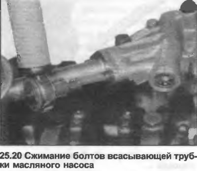
20. Position the new O-ring on the end of the suction tube. Mount the tube on the oil pump, insert the bolts and tighten them to the tightening torque specified in the Specification (photo).
21. Install the front crankshaft oil seal housing (without seal), together with a new gasket. Insert and tighten the bolts to the tightening torque specified in the Specification (photo).
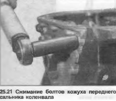
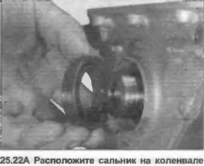
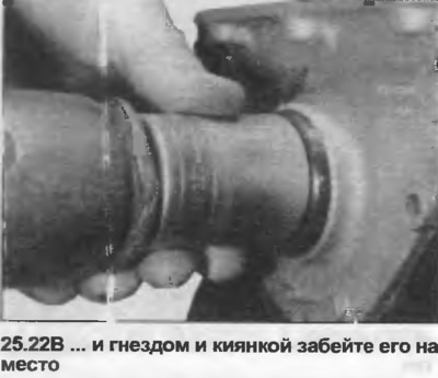
22. Lubricate the seal tabs and the outer rim of the new seat. Position the seal on the nose of the crankshaft. Using a suitable socket and mallet, tap the seal directly into the housing until it is flush with the outer edge (photo).
23. Install the crankshaft rear oil seal housing (without seal) together with a new gasket. Insert and tighten the bolts to the specified tightening torque Specification (photo).
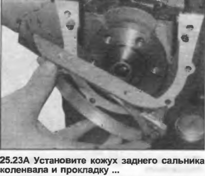
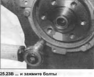
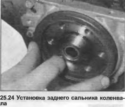
24. Lubricate the seal lugs and outer rim of the new seal. Position the seal on the rear crankshaft flange (photo), carefully tap it straight into the housing until it is aligned with the outer edge.
25. Turn the engine over and place the new gasket on the base of the block.
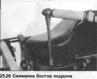
26. Install the pan, then insert and tighten the bolts in a diagonal sequence to the tightening force specified in the Specification (photo).
27. Support the engine in a standing position.
28. Apply a suitable insulator to the outside surface of the lower end of the dipstick tube. Use a mallet to tap the dipstick tube into the block.
29. Install the sprocket on the front end of the crankshaft.
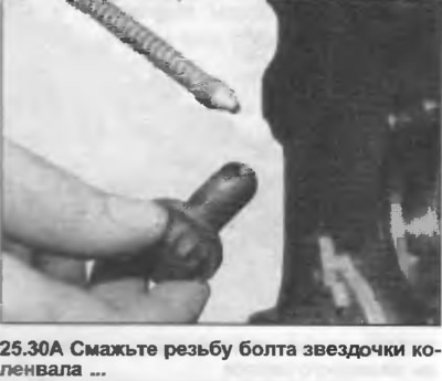
30. Lubricate the bolt threads, then insert and tighten it to the tightening torque specified in the Specification (photo). Lock the crankshaft while compressing with a long rod placed between the two bolts at the rear of the crankshaft.
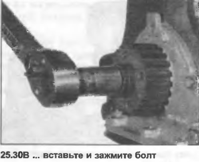
31. Lubricate the bearing journals on the intermediate shaft. Carefully insert the shaft into the block.
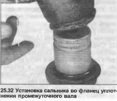
32. Lubricate the seal lugs and outer rim of the new intermediate shaft oil seal. Place the seal flange on a bench and use a socket and mallet to tap the seal into place (photo).
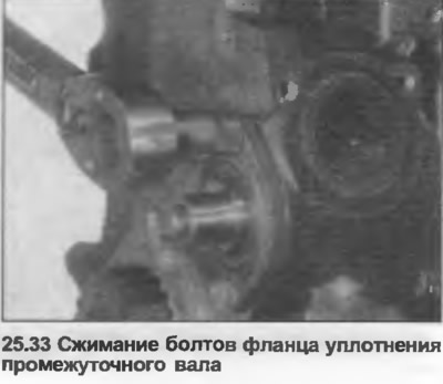
33. Position the new O-ring on the flange. Place the flange on the block, insert the bolts and tighten to the tightening torque specified in the Specification (photo).
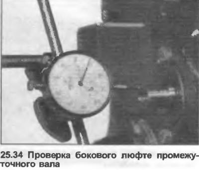
34. Using a micrometer, check that the intermediate shaft lateral clearance corresponds to the data in the Specifications (photo).
35. Install the right engine mount bracket hanger and rod to the block, insert the bolts and tighten to the specified tightening torque Specification.
36. Install the left engine mounting bracket hanger to the block, insert the bolts and tighten to the specified tightening torque Specification.
37. Install the generator mounting bracket, insert and tighten the bolts.
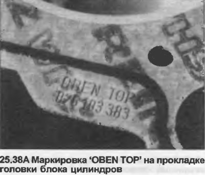
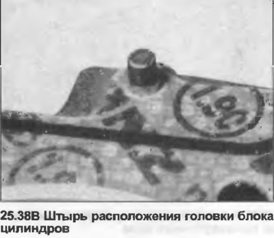
38. Make sure the top of the block is completely clean, then position the new gasket on it with the words "OBEN TOP" facing up. Make sure the location pins are in place (photo).
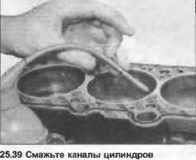
39. Turn the engine clockwise so that all pistons are positioned in the middle of the channels, pistons No.1 and 4 on the compression stroke. Inject oil into each cylinder (photo).
40. Check that the cylinder head surface is completely clean. Carefully lower the head onto the block. Do not use any compounds when connecting the cylinder head.
41. Insert the cylinder head mounting bolts together with the washers, initially tightening them by hand.
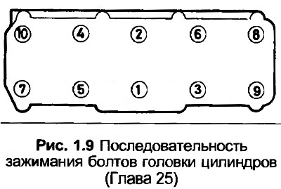
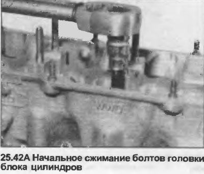
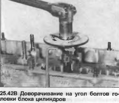
42. In the sequence shown in Fig. 1.9, tighten the bolts to the torque of stage 1 given in Specifications. Then tighten them with the torque of stage 2, and finally turn them half a turn (180°) without stopping (two times 90° is allowed) (photo).
43. Install the front engine lifting eye, tighten the bolt.
44. Install the rear timing belt cover, insert and tighten the bolts.
45. Turn the intermediate shaft so that the Woodruff key groove faces straight up. Insert the woodruff key into the groove.
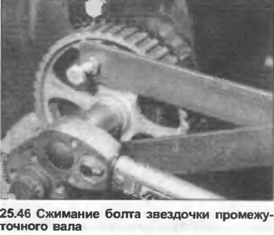
46. Install the sprocket on the intermediate shaft, engaging it with the woodruff key. Insert and tighten the bolt with the tightening force specified Specification. Lock the sprocket with a tool made as shown in the photo.
47. If necessary, check the camshaft side play before installing the hydraulic tappets. To do this, perform steps 49 and 50, then use a micrometer to check that the side play corresponds to the data in the Specifications. Remove the camshaft again and continue with the next step.
48. Lubricate the hydraulic lifters, then insert them into the pre-marked positions.
49. Lubricate the bearing journals on the camshaft, then lower the camshaft into place on the lifters, making sure the cams for cylinder #1 point up.
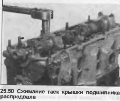
50. Install bearing caps No.2 and 5 (skip No.4). Install and tighten the nuts to the specified tightening torque Specification (photo) Make sure the covers are oriented correctly as noted when removed because they are slightly offset.
51. Install bearing caps No.1 and 3, install and tighten the nuts with the tightening force specified Specification.
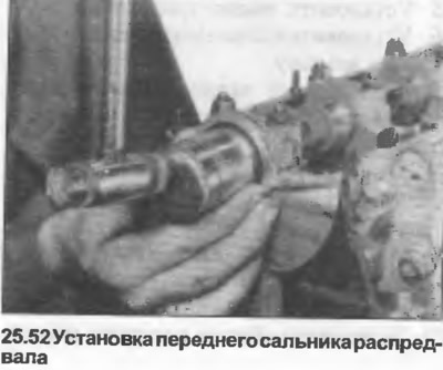
52. Lubricate the seal lugs and outer rim. Position the seal on the front end of the camshaft and use a socket and mallet to drive it straight into place until it is flush with the cylinder head surface (photo).
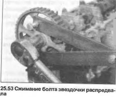
53. Insert the woodruff key into the camshaft groove. Position the sprocket on the camshaft, insert the bolt and washer, tighten the bolt to the tightening torque specified in the Specification, locking the sprocket with a tool as shown in the photo or similar.
54. Install the timing belt tensioner wheel and hub onto the stand at the front end of the cylinder head, then install the washer and nut.
55. Temporarily install the drive belt pulley onto the crankshaft sprocket in the previously marked position. Insert and tighten two diagonally opposite bolts.
56. Align the mark on the back of the camshaft sprocket with the top of the cylinder head on the left side.
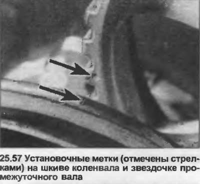
57. Turn the intermediate shaft sprocket until the mark aligns with the drive belt pulley. Turn the engine clockwise until the mark on the pulley aligns with the mark on the sprocket (photo).
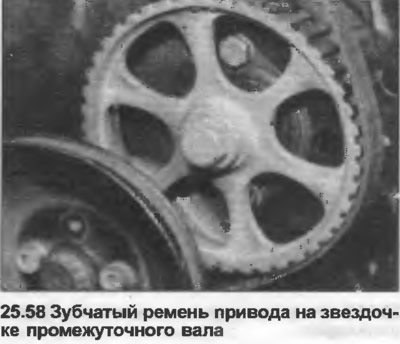
58. Position the timing belt on the crankshaft sprocket and intermediate shaft sprocket. If you are installing the old belt, make sure it is correctly oriented according to the previously made mark (photo).
59. Install the belt on the camshaft sprocket, then on the tensioner wheel and turn the hub clockwise, locking the belt in position (photo).
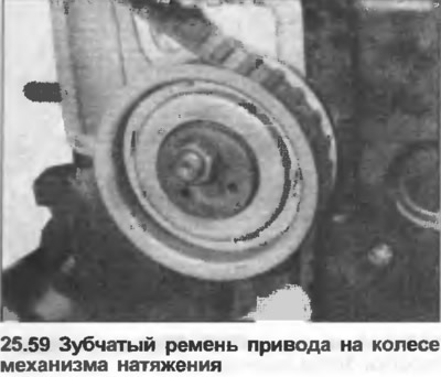
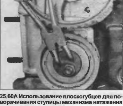
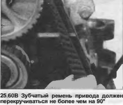
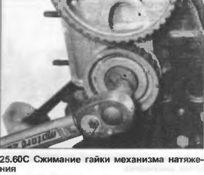
60. Using snap ring pliers or a suitable tool, turn the tensioner hub clockwise. Continue turning until the belt is tensioned so that it can only be twisted 90° at the midpoint between the intermediate shaft and camshaft sprockets. Tighten the tensioner nut, recheck the tension and timing marks (photo).
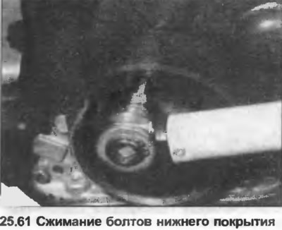
61. Unscrew the water pump pulley from the crankshaft sprocket. Place the special gasket in the lower cover of the toothed belt drive, then install the cover, insert and tighten the bolts (photo).
62.Install the water pump pulley onto the crankshaft sprocket in the pre-marked position. Insert and tighten the bolts.
63. Install the rubber plug on the rear of the cylinder head and the semi-circular gasket into the groove in the front camshaft bearing cover.
64. Install a new gasket onto the struts on top of the cylinder head.
65. Install the oil deflector.
66. Install the reinforcement strips and valve cover.
67. Position the ground clamp and wire tie down straps. Tighten the nuts.
68. Install the rear upper timing belt cover. Tighten the nuts.
69. Install the top drive cover and nut (where is it used). Secure with staples.
70. Install the water pump assembly with a new O-ring. Insert and tighten the bolts.
71. Install the special bolt securing the lower drive cover to the water pump assembly, tighten the nut.
72. Install the pulley onto the water pump. Insert and tighten the bolts.
73. Install the outlet housing to the rear of the cylinder head with a new O-ring. Insert and tighten the bolts.
74. Install the outlet pipe on the side of the cylinder head together with a new O-ring. Insert and tighten the bolts.
75. Install the oil filter housing onto the block with a new gasket. Insert and tighten the bolts.
76. Clean the mating surfaces of the new oil filter and housing, then lubricate the filter seal. Screw the filter into the housing, tightening it by hand.
77. Install the fuel container and hanger on the valve cover. Tighten the nuts.
78. Make sure the pins are installed on the back of the block. Install the spacer plate onto the pins.
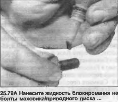
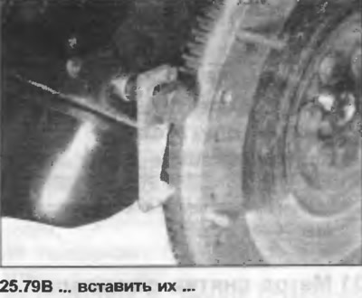
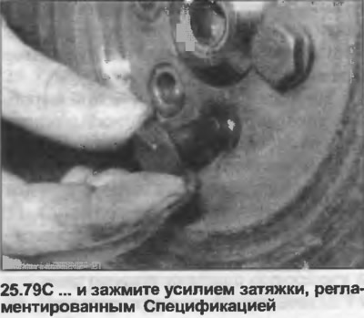
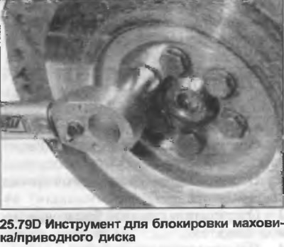
79. Position the flywheel/drive plate on the crankshaft. Audi recommends that the flywheel/drive plate bolts are always replaced after removal. Apply locking fluid to the threads, then insert and tighten the bolts to the specified torque Specification, locking the flywheel/drive plate. Install the bolt in the cylinder block and use a screwdriver to secure the flywheel/drive plate to the toothed ring. You can also use the tool shown in the photo. Make sure that the pre-made marks are aligned.
80. If at least one hydraulic tappet has been replaced, do not start or crank the engine for at least the next thirty minutes. This is necessary to allow excess oil to flow out of the tappet. If this precaution is not taken, there is a risk of the valve striking the piston.
The article was copied from the website: AUDIMANUAL