



Note: If necessary, temporarily install the camshaft and check the camshaft side play before installing the hydraulic lifters (see Specifications).
1. Lubricate the hydraulic tappets and insert them into the pre-marked positions.
10 valve engines
2. Lubricate the bearing journals on the camshaft, then lower the camshaft into place on the lifters, making sure the No.1 cylinder cams point up.
3. Install bearing caps #2 and #4, tighten nuts in diagonal sequence to Specification torque. Make sure caps are oriented correctly as noted when removed because they are slightly offset.
4. Install bearing caps No.1 and 3 in the same manner.
20 valve engine
5. Lubricate the bearing journals on the camshafts.
6. Position the chain on the sprockets so that the marks are positioned as shown in Fig. 1.20, then lower the camshafts into place.
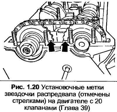
7. Install bearing caps No.6, 8 and 10, tighten the nuts in a diagonal sequence with the tightening torque specified in the Specification.
8 Install bearing caps No.7 and 9 in the same way, then bearing caps No.1, 3 and 5, and finally caps No.2 and 4.
All engines
9. Lubricate the projections and outer rim of the new oil seal. Position it on the front end of the camshaft and use a socket and mallet to tap it into place until it is flush with the cylinder head surface. Make sure the oil seal does not block the oil return hole.
10. Position the woodruff key then install the camshaft sprocket. Insert and tighten the center bolt to the specified torque Specification.
11. Install the toothed drive belt as described in Chapter 40.
12. Install the valve cover with new gaskets.
13. Restore the actions of the preliminary procedure given at the beginning Chapters 35. If even one hydraulic lifter has been replaced, do not start or crank the engine for the next thirty minutes. There may be excess oil in the lifter, which will cause the valve to strike the piston.
The original material is located on the website: AudiManual.ru