1. The sunroof has four drain hoses, one on each corner. The front hoses run inside the front door pillars; rear hoses - inside the C-shaped column (Sedan) or D-shaped (Avant).
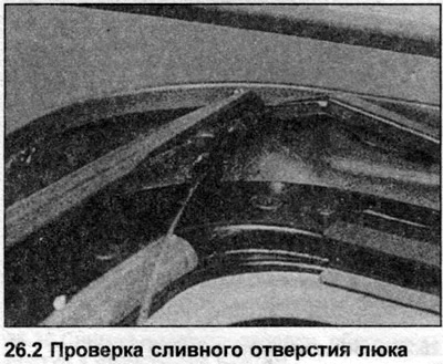
2. The drain hoses must be clean, check them periodically along their entire length (photo). If the hoses become clogged, water can leak into the cabin.
Seat belts (all models) - care and maintenance
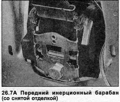
3. Maintenance is limited to checking the operation of the seat belt clamps and tensioners, the inertia drum. In case of failure, replace the belt completely. Belts that have been subjected to dynamic loads should also be renewed.
4. Do not paint the belts or attempt to clean them with solvents. Clean the belts periodically with a mild soap solution. After cleaning, unroll the belts until they dry.
Seat belts (all models) - removal and installation
5. Design varies depending on trim and equipment, but the following guidelines apply to all models.
6. Remove interior trim as necessary to access drum and belt assemblies.
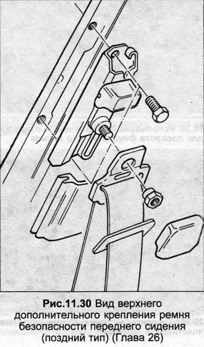
7. Remove the mounting nuts or bolts, noting the installation positions of all gaskets and washers (photo).
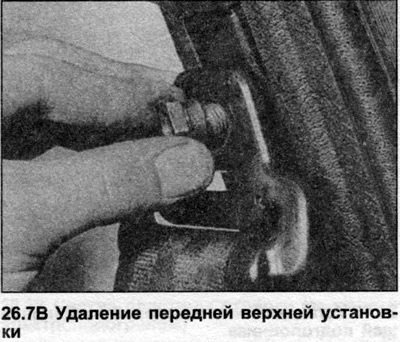
8. After repair, assembly is carried out in the reverse order, tightening the mounting bolts with the tightening force specified in the Specification.
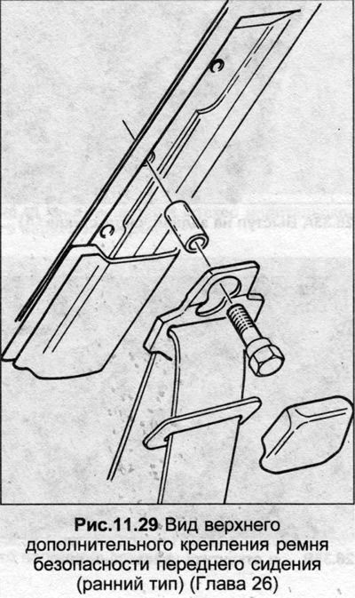
9. An exploded view of the top mount type used on later models is shown in Figs. 11.29 and 11.30.
Back seat (Sedan with headrests) - removal and installation
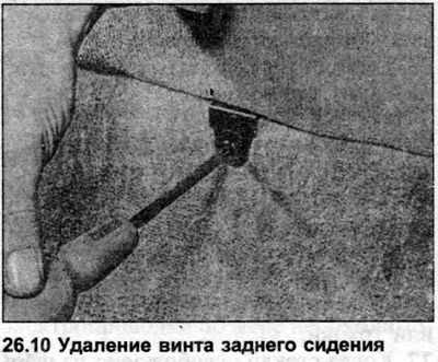
10. Remove the two screws that secure the seat cushion (photo). Lift the cushion up and forward to remove.
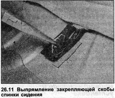
11. Bend back the two brackets that secure the seat back base (photo).
12. Remove the lieutenant colonels as described later in this Chapter.
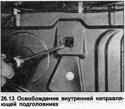
13. Release the cotter pins of the headrest guides by pressing on them with a screwdriver (photo).
14. With the guides released, lift the seat back and remove it. Remove the guides.
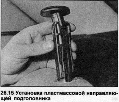
15. When installing, place the seat back correctly, insert the extenders and squeeze them (photo).
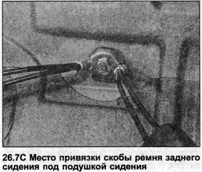
16. Lean over the two clips at the base of the seat back and make sure the seat belt clips are not caught behind the seat back.
17. Install the seat cushion and headrests.
Headrests (all models) - removal and installation
18. Remove the stud clip from each headrest guide using a small screwdriver (photo).
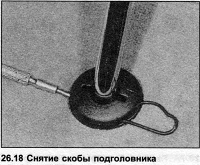
19. Lift the headrest along the guides to remove it.
20. After repair, insert the headrest into the guides. Insert the stud clips and push them.
Rear view mirror (all models) - removal and installation
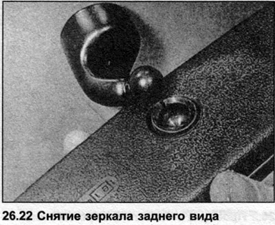
21. Remove the screw (where it is installed near the mirror hinge.
22. Remove the mirror from the installation (photo).
23. The mirror installation is connected to the windshield with a special glue; do not attempt to remove it. If the unit accidentally comes off, use a suitable adhesive to secure it back in place.
24. Install the mirror using a small amount of silicone based lubricant on the hinge, then place the mirror.
25. Repair and tighten the fastening screw where applicable.
Exterior mirror glass (all models) - replacement
Mechanical adjustment
26. Carefully pry the glass off the mirror housing using a wooden or plastic wedge. Protect the paint on the mirror housing with a piece of tape or rag.
27. When the glass is released from the hinge, disconnect the regulator rod and the spring from the inner end. Remove the glass.
28. Repair the regulator rod and spring. Install the glass into the hinge and press in the center until it snaps into place. Use gloves to prevent injury from accidental glass breakage.
Electrical adjustment
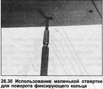
29. The glass is fixed with a special device. The rotating ring and internal components are shown in the photo.
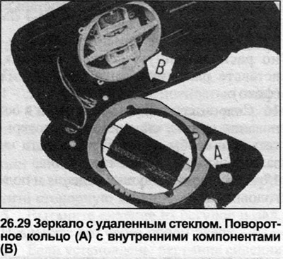
30. Insert a small screwdriver through the hole in the back of the mirror and turn the locking ring (photo). The ring has teeth to make this easier.
31. If the glass has heating elements, disconnect the wiring connectors, noting their locations.
32. To install the mirror glass, first connect the heater connectors (where it is applied).
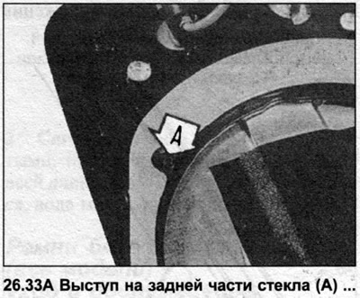
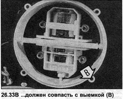
33. When installing the glass on the mirror housing, it is important that the locking devices on the back of the glass match the grooves on the internal components (photo). It is impossible to check the correct inclusion visually.
34. Secure the glass by rotating the ring using a small screwdriver inserted through the hole in the back of the mirror.
Outside mirror (mechanical adjustment) - removal and installation
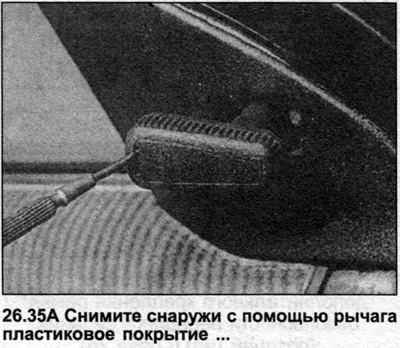
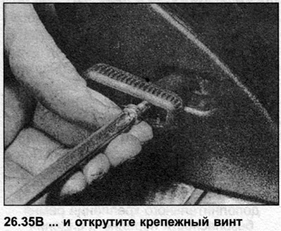
35. Remove the plastic covering on the control handle using a lever. Unscrew the screw and remove the button (photo).
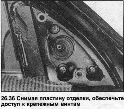
36. Remove the trim plate to access the mounting screws (photo). The trim plate may be secured with a screw, or it may simply unclip.
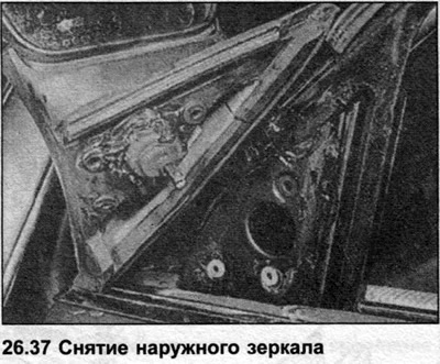
37. Support the mirror and remove the three mounting screws. Remove the mirror by removing the rubber cover from the door. Be careful not to lose the screws or spacers in the door cavity (photo).
38. When installing, use liquid soap to make installation easier.
Outside mirror (electrical adjustment) - removal and installation
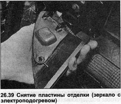
39. Remove the trim plate, securing screw (photo).
40. Unscrew the screws that secure the mirror.
41. Roll down the door window and pull the mirror out of the door.
42. Support the separated mirror assembly.
43. Raise the window.
44. Disconnect the negative battery terminal.
45. Remove the door trim assembly as described later in this Chapter. Disconnect the multi-plug electrical wiring as necessary.
Driver's outside mirror
46. Remove the lower portion of the instrument panel. Disconnect the multi-plug electrical wiring as necessary.
47. Remove the screws securing the hood release lever and trim group and remove the trim.
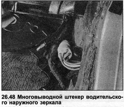
48. Now you have access to the multi-pin plug for the mirror wiring in the upper corner (photo).
49. Disconnect the multi-plug and pass it through the protective covering and the door, removing all cable clamps.
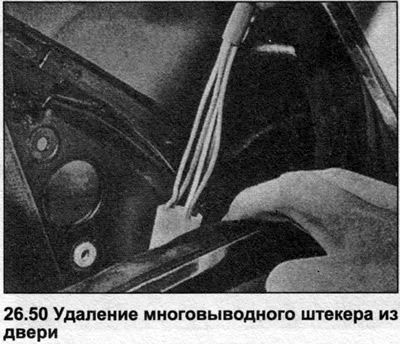
50. Pull the multi-plug out through the wide opening (photo). The mirror is now completely disconnected. Passenger Outside Mirror
51. The procedure is the same as for the driver's outside mirror, but with the following differences.
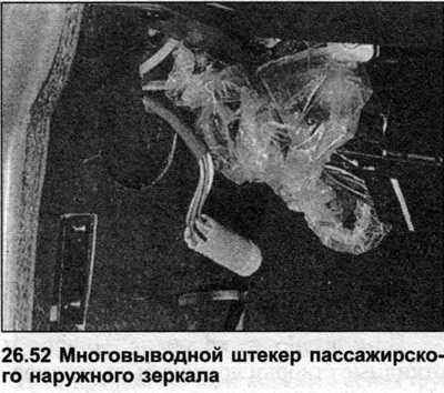
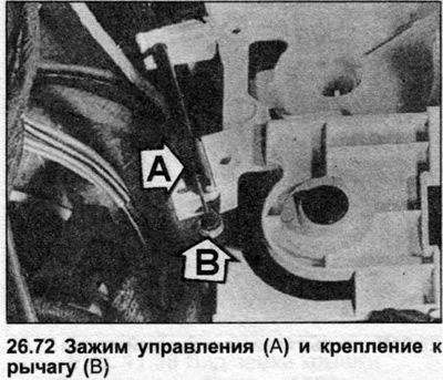
52. To access the multi-pin electrical wiring plug, it is necessary to remove the trim group and lift the ignition control unit from the suspension (photo).
Any mirror
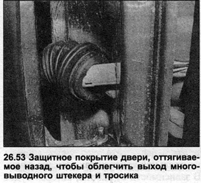
53. Installation is the reverse procedure of removal. Make sure you use clamps to secure the cable inside the door. Passing the multi-pin plug and cable through the protective covering will be easier if one end of the protective covering is moved out of the trim group (photo).
54. Temporarily reconnect the battery and check that the mirror is working properly before installing the door trim.
Air Conditioner - Precautions and Maintenance
55. The following points are additional to the information in Section 11.
56. Run your air conditioner for at least five minutes every month, even in cold weather. This ensures that the lubricant is continuously distributed throughout the system.
57. Do not operate the system if refrigerant leakage is obvious or the system is discharged. In this case, remove the compressor drive belt to prevent damage.
58. Check the coolant level periodically and add as needed. Some leakage is normal over a long period of operation, even under normal use.
Automatic Air Conditioner - General Description
59. Later models can be equipped with a fully automatic air conditioner. With this system, if a certain air temperature in the cabin has been pre-selected, the air conditioner software controls the temperature control flap and changes the fan motor speed automatically to maintain the desired temperature. Manual control is also possible, bypassing the automation.
60. If there is a fault in the system, check that the cable from the program device to the temperature control flap is not loose or tight. Also check the flap itself.
61. Further investigation should be carried out by a specialized workshop.
Procon-ten Security System - General Description
62. The Procon-ten (Programmed Contraction and Tension) safety system is a series of cables connected to both the front seat belt inertia drums and the steering column. The cables pass around the anchor suspension on the right and connect to the chassis elements, the guide suspension on the left connects the chassis elements and the tensioner suspension on the gearbox housing.
63. In a frontal impact where the engine/transmission block is located, the rear cables will be automatically tensioned by the movement of the engine/transmission block and the steering column (damper) will collapse and retract the seat belts.
64. The Procon-ten system is not installed as standard.
Procon-ten Security System - Inspection
65. If any part of the system has been activated in an accident, the entire system must be replaced, including the steering column. The seat belt, retractor drum and tensioner cable must also be replaced.
66. Check the paint color spot on the steering column seal to detect any movement due to paint damage.
67. If any of the seat belts cannot extend or retract, the system will turn on.
68. If any individual component of the Procon-ten system becomes unusable during operation, it can be replaced separately.
Heater control drive (rotary, since 1988) - removal and installation
69. The drive is located under the central console.
Heater control unit and cables (rotary, since 1988) - removal and installation
70. Remove the heater control and release the control assembly from the center console as described previously. Depending on the work to be performed, the entire console may not need to be removed.
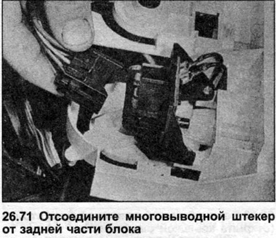
71. Disconnect the multi-pin plug from the back of the unit (photo).
72. Unclip the control cables from the unit, then disconnect their ends from the control mechanism (photo).
73. Release the ends of the heater cables, noting that the temperature control cable end and the air cable end are accessible from the collection chamber in the engine compartment.
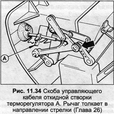
74. When installing the cables, the drive and flaps must be installed as follows before installing the mounting brackets:
Temperature control cable
The hot temperature control button controls the flap control lever located on the engine bulkhead.
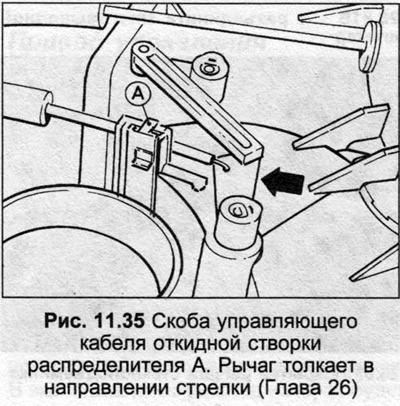
Distributor flap
Distributor control handle to instrument panel air outlet 4, distributor controls flap remote from engine bulkhead.
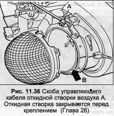
Air supply adjustment cable
Fan control to "0", switch flap closed.
75. Installation is the reverse procedure of removal.
Interior door trim group (since 1988) -removal and installation Front door
76. On later types, remove the cover on the outside mirror housing.
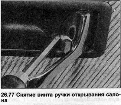
77. Pull the door release handle outward, remove the screw shown, then push the assembly out of the trim group (photo).
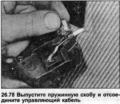
78. Disconnect the assembly from the control cable, having first removed the spring clips (photo).
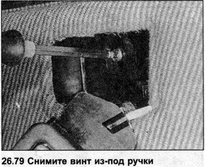
79. Remove the screw from under the handle (photo).
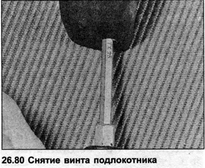
80. Unscrew the screws securing the armrest and remove the armrest (photo).
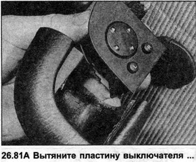
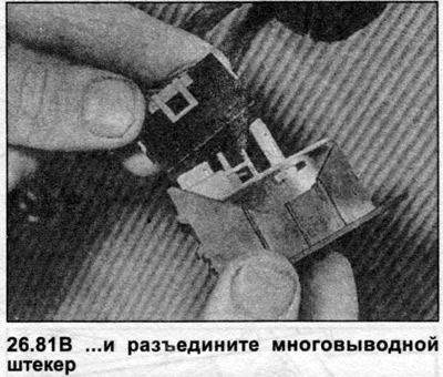
81. Where installed, pull the switch plate out of the armrest and disconnect the multi-pin plug (photo).
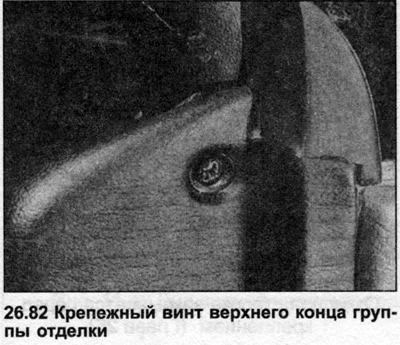
82. Remove the screw from the top of each group (photo).
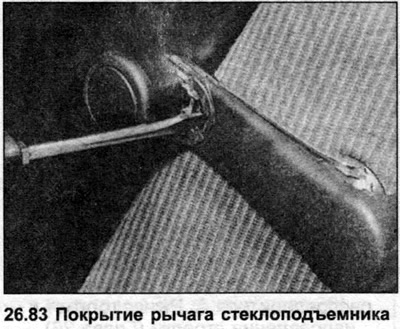
83. For manual windows, use a lever to remove the handle trim cover by inserting a screwdriver behind the handle (photo).
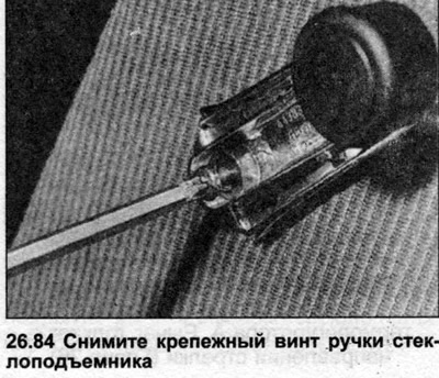
84. Remove the window lift handle mounting screw and take out the handle (photo).
85. Where used, remove the door-opening interior light from the outside using the lever and disconnect the wires.
86. Carefully remove the door trim group using a lever. All brackets and the door group must remain intact.
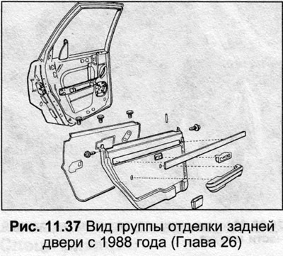
Back door
87. The procedure is similar to that described for the front door, but the armrest is slightly different. On Avant models, the rear speaker must be disconnected or removed as necessary.
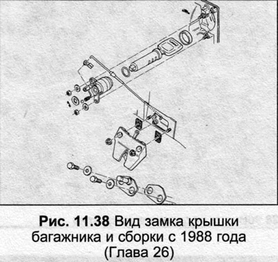
Trunk lid lock (since 1988) — general description
88. Since 1988 the trunk lid lock has again been mounted on the rear panel near the tail light, but the general location of the lock and latch is similar to earlier models.
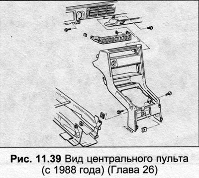
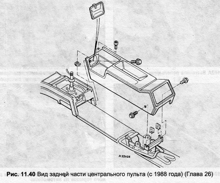
Central control panel (since 1988) - removal and installation
Note: Several types of center console may be installed depending on trim level and model. On later models, the console is in two pieces, with the rear section removed before the front section.
89. Disconnect the negative battery terminal.
90. Remove both front seats for easy access, or move the seats completely.
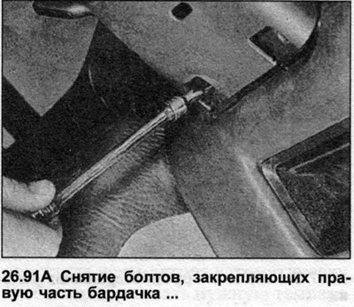
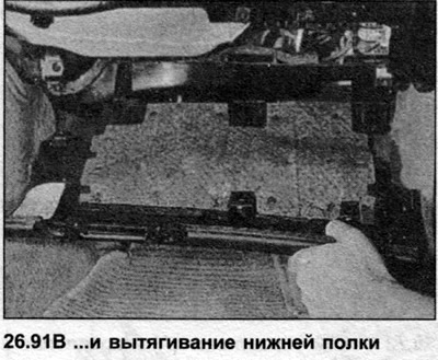
91. Remove the clamp bolts and remove the right glove compartment shelf (photo).
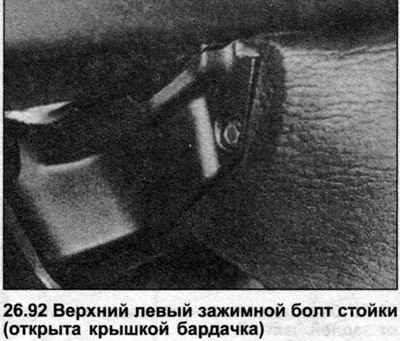
92. Remove the upper bolts from the left and right side of the console. The left bolt is accessible after opening the glove compartment lid (photo).
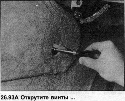
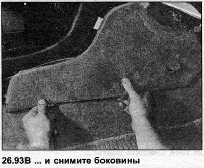
93. Unscrew and remove the two side panels (photo).
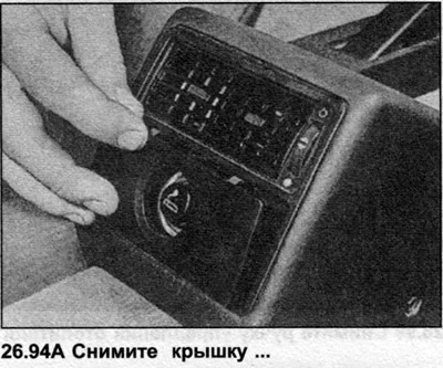
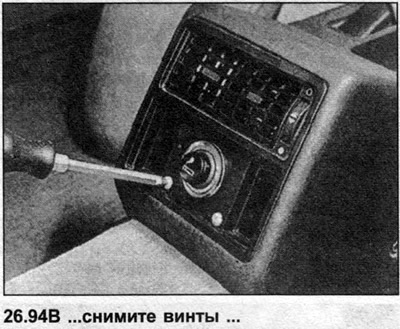
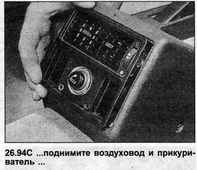
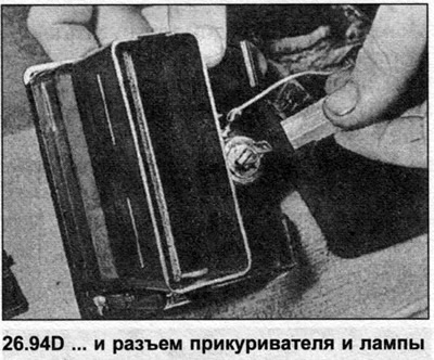
94. Remove the rear cigarette lighter from the outside using a lever, remove the screws and lift the air duct and cigarette lighter. Disconnect the cigarette lighter and lamp (photo).
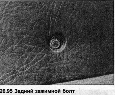
95. Remove the bolt from each rear side of the console (photo).
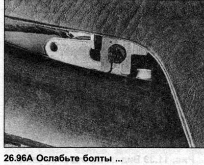
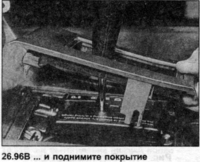
96. Loosen the bolts securing the gear selector/shift lever cover and lift (photo). It may be necessary to unscrew the lever knob to remove the cover.
97. Remove the radio.
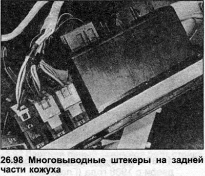
98. Move it out (push) top cover of the switch from the central console. If the cover or switches are to be removed, disconnect the switches and digital timer (photo).
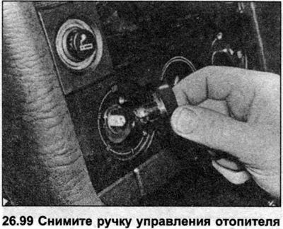
99. Remove the heater control knobs (photo).
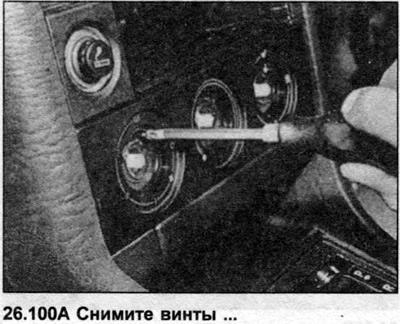
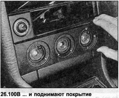
100. Remove the screws from the heater group (photo).
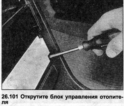
101. Unscrew the heater control unit from the console (photo).
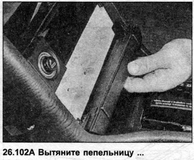
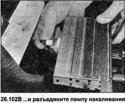
102. Pull out the front ashtray and disconnect the ashtray lighting bulb (photo).
103. Disconnect the front cigarette lighter.
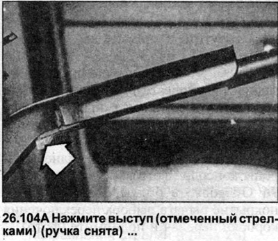
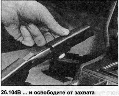
104. Spread the handbrake lever fully and release the plastic grip of the handle, lowering the protrusion on the back side. Remove the grip from the lever (photo).
105. Remove the console above the handbrake lever (photo).
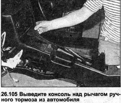
106. Installation is the reverse procedure of removal.
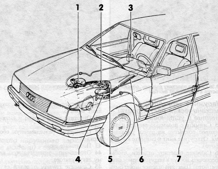
Fig. 11.31 Procon-ten security system (Chapter 26)
1 - Anchor hanger
2 — Cable tensioning mechanism
3 - Seat belt inertia drum and cable.
4 — Guide rail suspension
5 — Cable retainer
6 — Steering column cable
7 — Seat belt inertia drum and cable
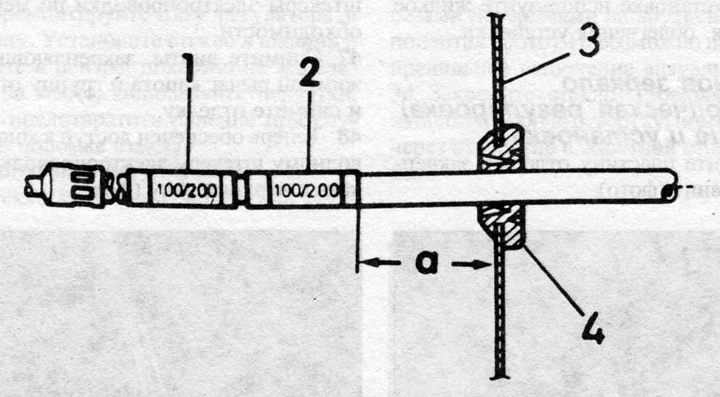
Fig. 11.32 Identification of the seat belt drive cable (Chapter 26)
1 — Mark only on right-hand drive vehicles
2 - Mark on all vehicles
3 - Partition
4 — Sealing ring
Size a = 60-70 mm
Label color:
White - 012 KPP
Brown - 016 manual transmission
Green - 087/089 Automatic Transmission
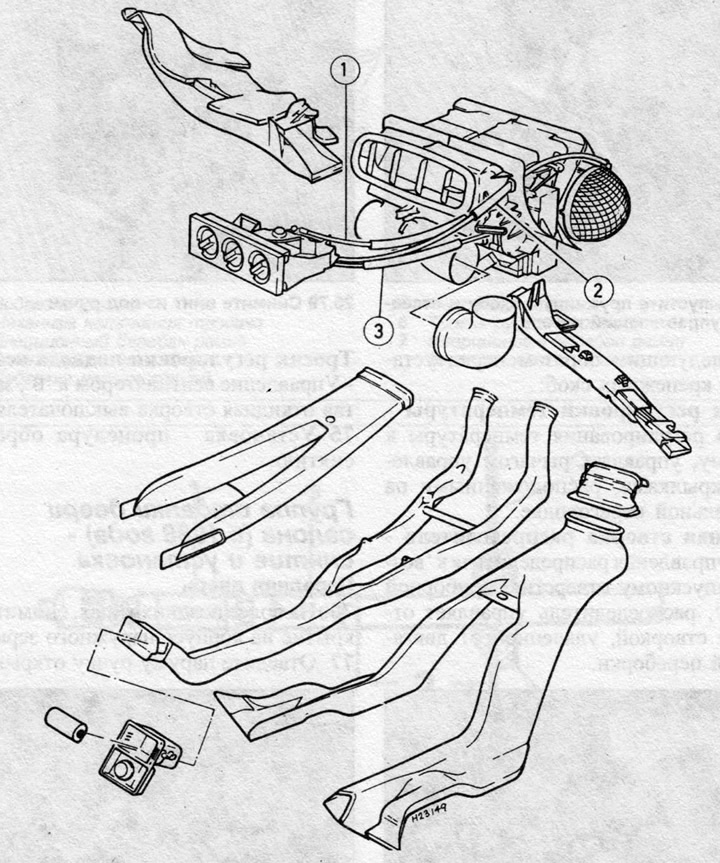
Fig. 11.33 Assembly view of the heater with a rotary drive (Chapter 26)
1 - Thermostat control cable
2 - Fresh air flap control cable
3 — Control cable for the distributor flap