
Table of contents: Mechatronic transmission with… ↓ Removal and installation the ATF pan ↓ Removal and installation the ATF… ↓ Removal and installation of the J743… ↓
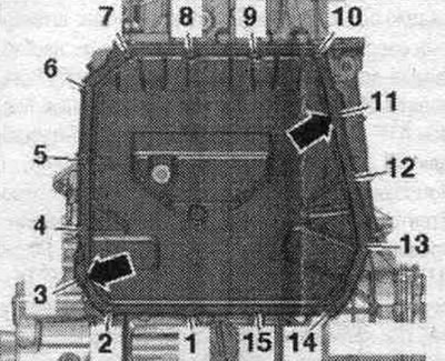
Mechatronic transmission with twin-disc clutch "J743"
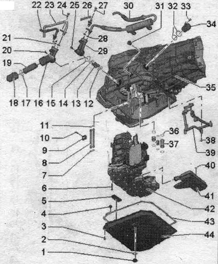
1. ATF drain hole threaded plug.
2. Sealing cuff: replace.
3. Bolt.
4. Expansion rivet: in original equipment for fastening the ATF pan gasket; not required for installation.
5. Magnet: 2 pcs., insert into the oil recess. aTF pan; pay attention to the tight fit of the ATF to the oil pan.
6. Bolt: replace.
7. O-rings: replace.
8. ATF pressure pipes (clutch release force).
9. Mounting plate: for ATF pressure pipes (clutch release force).
10. Bolt: 10 Nm.
11/12. Replace sealing rings.
13. ATF oil lines: different designs depending on the year of manufacture.
14. Sealing rings: replace.
15. Sealing ring: replace; different designs depending on the year of production.
16. ATF replaceable filter housing: for gearboxes with a replaceable ATF filter, different designs depending on the year of manufacture.
17. Sealing ring: for gearboxes with replaceable ATF filter; replace.
18. ATF replaceable filter cover: for gearboxes with replaceable ATF filter.
19. Replacement ATF filter: replacement when replacing ATF and after repairs to the gearbox; take into account compliance.
20. Bolt: 3 pcs., 10 Nm, for gearbox with replaceable ATF filter.
21. O-rings: replace; for gearboxes with replaceable ATF filter.
22. ATF oil return line: for gearboxes with replaceable ATF filter.
23. ATF oil supply line: for gearboxes with replaceable ATF filter.
24. Bolt: for gearbox with replaceable ATF filter.
25. Bolt: 3 pcs., 10 Nm, for gearbox with ATF main filter.
26. ATF oil return line: for gearboxes with an ATF main filter.
27. Bolt: for gearbox with ATF main filter.
28. O-rings: replace; for gearboxes with ATF main filter.
29. Connector for ATF lines: for gearboxes with ATF line filter.
30. ATF main filter: when replacing the gearbox and repairing the gearbox, replace the ATF main filter.
31. Threaded plug for filling and inspection hole for ATF oil.
32. Sealing rings: replace.
33. Bolt: 8 Nm.
34. Plug connector: to remove, unscrew bolt "pos. 33" and turn the plug connector counterclockwise.
35. Carter KP.
36. Sealing rings: replace.
37. ATF oil lines: different designs depending on the model, take into account compliance.
38. Bolt: 8 Nm.
39. Cabling of speed sensors.
40. Sealing ring: replace.
41. ATF suction filter.
42. Mechatronic transmission with dual clutch "J743": after replacing the Mechatronic transmission with dual clutch "J743", it is necessary to perform the corresponding "Guided function" using the diagnostic system; disconnecting the printed circuit board of the Mechatronic gearbox with dual clutch "J743".
43. Gasket: replace.
44. ATF oil pan.
Torque and sequence, oil tightening. aTF pan
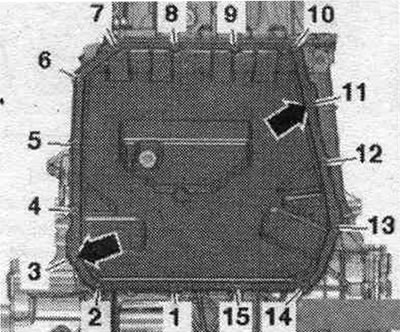
Tighten the bolts in 2 stages as follows.
1. Screw in the "arrow" bolts by hand.
2. Tighten bolts "1...15" crosswise in several stages with a torque of 10 Nm.
Mechatronics - torque and sequence, tightening
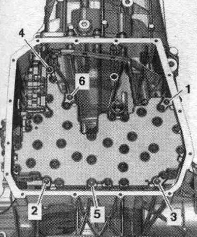
Tighten the bolts in sequence. "1...6" with a torque of 10 Nm.
Removal and installation the ATF pan
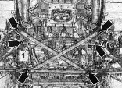
Remove sound insulation "1" and "2". Remove the subframe cross braces. If the powertrain support, steering gear or subframe crosspiece is incorrectly installed, the vehicle must not be placed on the wheels.
Drain the ATF. Do not start the engine if there is no ATF in the transmission. Loosen bolts "1...15" crosswise. Remove the ATF oil pan. Ignore the arrows.
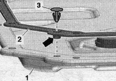
Installation
Installation in reverse order. Replace the ATF pan bolts and gasket. Clean the sealing surfaces. Insert the "arrow" portion of the new gasket "2" into the ATF pan "1". If present, secure the gasket to the ATF pan with clamps "3".
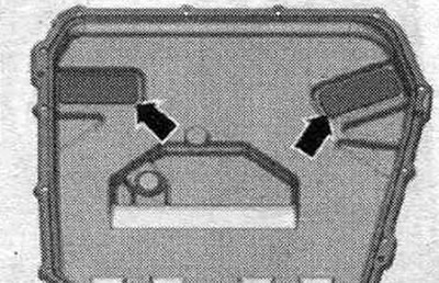
Clean the "arrow" magnets in the ATF pan. The magnets should be fully seated against the ATF pan.
Tighten the oil cap bolts. aTF pan. Install the subframe cross braces. Install diagonal braces. Fill with ATF.
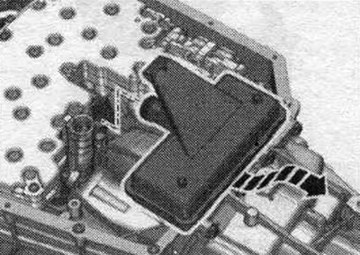
Removal and installation the ATF intake filter
Remove the ATF oil pan. Place a tool for filling and extracting oil under the transmission. Carefully remove the ATF intake filter towards the rear from the Mechatronic "arrow".
Installation
Installation in reverse order. Install the O-ring "2" of the rear support of the ATF suction filter "1". Carefully insert the suction flange of the ATF suction filter until it stops in the oil hole. pump. The support with an O-ring seal must fit into the hole in the gearbox housing.
Install the ATF oil pan. Fill with ATF.
Removal and installation of the J743 Mechatronic transmission with a dual-disc clutch
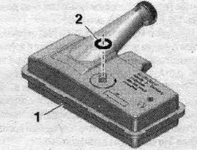
The checkpoint is installed. Move the selector lever to position "P". Turn off the ignition. Before working with electrical connectors, the specialist must "discharge electrostatic charge". Disconnect the gearbox plug connector by turning the rotary clamp counterclockwise "arrow".
Unscrew bolt "1". Turn connector block "2" counterclockwise "arrow" and remove it.
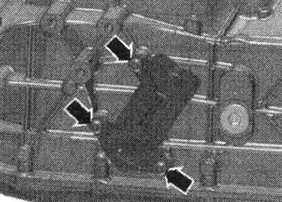
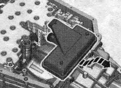
Unscrew the bolts "arrows" and pull out the ATF line connecting element slightly. The illustration shows the connecting element with the ATF lines removed. Remove the ATF oil pan.
Place a device for filling and pumping out oil under the gearbox. Carefully remove the ATF filter in the rear direction from the Mechatronic "arrow".
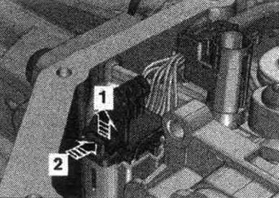
Disconnect the connector by pulling out the stopper "arrow 1" and pressing the locking mechanism down "arrow 2".
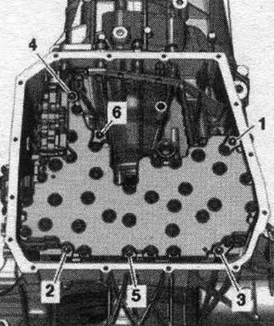
Remove screws "1...6". Only screws "1...6" may be removed. Removing other screws may result in deterioration of the mechatronic system or its separation. Avoid damaging the sealing surface. The mechatronic unit is partially secured to the gearbox. If the mechatronic unit needs to be removed, the second mechanic must hold it to prevent it from falling out. Alternatively, when unfastening, you can slightly tighten bolts "1" and "2" to secure the Mechatronic. Remove Mechatronic. Place the Mechatronic unit only with the side with the bolts facing down.
Installation
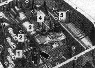
Replace Mechatronic O-rings and bolts. Do not bend the ATF line bracket. Unscrew the bolt "arrow". Remove the ATF lines "1" and "2". Remove the ATF lines "3...5". Replace the seal. rings and install the ATF lines. Tighten the "arrow" screw. Before installing the mechatronic module for the J743 dual-clutch transmission, ensure that all shift forks and fork hydraulic valves are in the center position.
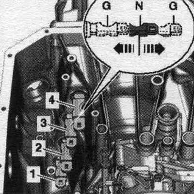
Adjusting the shift forks
First, check the positions of the shift forks "1...4" by hand. Each shift fork has three positions: gear engaged "G", neutral "N" (middle position), the gear is engaged in "G". Alternately shift each of the 4 shift forks once to each "arrow" position. Then return all the shift forks to the "middle" position "N".
Adjusting the gear regulator
Depending on the production date of the Mechatronic, the gear shifters must be adjusted differently. The year of manufacture is indicated on the Mechatronic "arrow" marking.
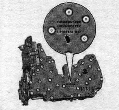
Mechatronic Markings: Explanations Using the Example "L31B1138"
- L: Year of production: L = 2010, K = 2009, J = 2008... etc.
- 31: Calendar week in the year of release.
- B1: Marking of the daily work shift of the manufacturer: Monday: shift 1 = A1, shift 2 = B1, shift 3 = C1; tuesday: shift 1 = D1, shift 2 = E1, shift 3 = F1; wednesday: shift 1 = G1, shift 2 = H1, shift 3 = L1... etc.
- 138: Current factory shift number for the day, here 138th Mechatronic shift B1.
Starting with Mechatronic "L31 B1138" the gearshift switches must be adjusted with a different setpoint. Mechatronics marked, for example, "L31A1140" is produced before Mechatronics "L31B1138" because it was produced in the 1st shift (A1) on Monday. Mechatronic with marking. eg "L31C1009" was produced after Mechatronic "L31B1138" because it was produced in 3rd shift (C1) on Monday.
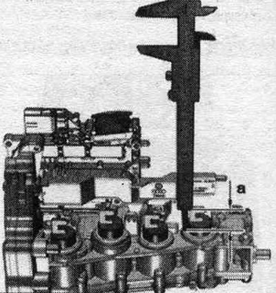
Set the 4 fork hydraulic drive valves on the back of the Mechatronic to the "middle position" for dimension "a" by carefully removing or inserting the hydraulic drive valves.
For mechatronics with markings up to "L31 B1137": distance "a" = 28 mm. For mechatronics with markings starting from "L31 B1138": distance "a" = 32 mm.
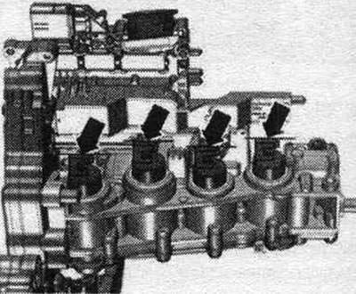
Align the "arrow" grips of the fork hydraulic valves so that they fit into the lugs of the shift forks during installation.
Install the mechatronic unit into the transmission housing. The mechatronic unit should fit easily into the holes in the transmission with its mounting bushings. If the mechatronic unit is difficult to insert, it's likely that one of the shift forks or the fork's hydraulic valve is not in the center position. Check and adjust the middle position if necessary.
After replacing the Mechatronic: Shine a flashlight through the hole between the Mechatronic and the gearbox housing and check all gear switches. All 4 driven discs of the gear shifter must be fixed in the corresponding lugs of the gear shift forks. Tighten the Mechatronic bolts. Installation in reverse order. Ensure that the electrical plug connections of the Mechatronic are correctly and securely fastened. Perform the necessary steps after connecting the battery. Install the ATF filter. Install the ATF oil pan. Add ATF. After replacing the mechatronic module for the dual-clutch transmission "J743," perform the corresponding "Guided Function" using a diagnostic tester. Check the transmission fluid (MTF) level and add more. Oil (MTF) must not be confused with ATF oil. Oil temperature approx. 20°C (room temperature). Place the car on a lift or in a pit so that it stands horizontally. The VAS 6617 manual oil pump must be clean and, if necessary, flushed with oil (MTF). Mixing with other oils is not permitted. The gearbox must remain inoperative for at least 15 minutes to ensure equalization of the oil level in the internal circuit. Remove rear noise insulation "2".
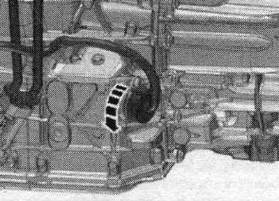
Cars with an ATF main filter "arrow" on the left rear of the gearbox
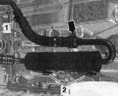
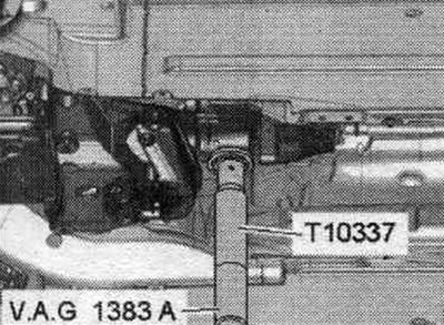
Install the "T10337" gearbox support on an engine and gearbox jack and place it underneath the gearbox. Raise the gearbox slightly. When removing the transmission tunnel crossmember to check the oil level (MTF) and add oil, it is necessary to return the transmission to its mounting position after removing the transmission tunnel crossmember. This is the only way to properly adjust the oil level. Remove the tunnel cross member.
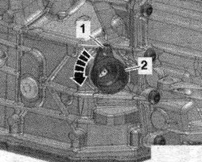
Unscrew bolts "2" and push the ATF main filter to the side. "Pos. 1" and "arrow" should not be taken into account. The ATF main filter must be moved aside to provide access to the oil filler and inspection plug (MTF).
Cars without an ATF main filter on the left rear of the gearbox
On vehicles without an ATF main filter, there is no need to remove the tunnel crossmember on the rear left side of the gearbox. To prevent oil (MTF) from getting into the upper lugs of the tunnel support, place a rag on the tunnel support. Place a suitable rag on the tunnel crossbar.
All
Place a device for filling and pumping out oil under the gearbox. Unscrew the filler and inspection hole plug "arrow" on the side of the gearbox housing.
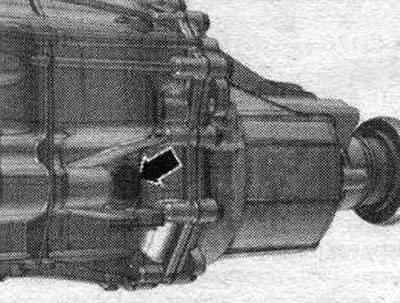
The oil (MTF) should reach the lower edge of the inspection/filler hole. If the oil level (MTF) is below the lower edge of the inspection/filler hole: Using the VAS 6617 hand oil pump, slowly fill in the oil (MTF) until it flows out of the inspection and filler hole. Repeat this process gradually every 15 seconds until the oil is drawn into the transmission. To ensure even filling of the transmission oil chambers, observe the waiting time. Tighten the screw plug. The rest of the installation is carried out in reverse order, taking into account the following.
Cars with an ATF main filter "arrow" on the left rear of the gearbox
Screw in bolts "2". Install the tunnel cross member.
Cars without an ATF main filter on the left rear of the gearbox
On a car without an ATF main filter, it is necessary to clean the tunnel cross member on the rear left side of the gearbox. Clean the tunnel cross member and remove oil.