
Table of contents: Pressure relief in a high pressure… ↓ Overview of installation locations… ↓ Oil pressure regulating valve "N428"… ↓ Installation location diagram (CFKA,… ↓ Installation location diagram ↓
Pressure relief in a high pressure area
Attention! The injection system is divided into a high-pressure circuit (max. about 140 bar) and low pressure circuit (about 7 bar). Before disconnecting a high pressure part - for example, removing the high pressure pump, fuel metering unit, injectors, fuel lines or fuel sensor. pressure "6247" - it is necessary to reduce the fuel pressure in the high-pressure section to a residual pressure of approx. 7 bar. The procedure for this is described below.
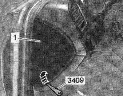
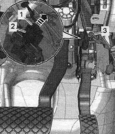
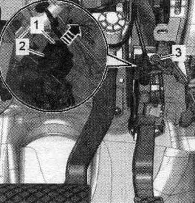
Connect the tester. Start the engine and let it idle. Select the "Engine Electronics" function in Self-diagnosis mode. Then select the "Measured Values Block" item. Select "Fuel Pressure" in the list. Lift the trim "1" on the left and right on the front panel, for example with a wedge "3409" "arrow".
With the engine idling, remove the fuel control unit fuse. pump "J538". After removing the fuse, the power supply to "terminal 30" of the fuel control unit is cut off. pump "J538". Monitor the pressure readings on the diagnostic tool. The fuel pressure drops very quickly because the mechanical high pressure pump is now no longer receiving fuel from the fuel pump. pre-feed pump "G6". Turn off the ignition as soon as the fuel pressure drops to approximately 8 bar.
Do not allow the fuel pressure to drop below 6 bar, otherwise the engine will stall (risk of damage to the catalyst). After releasing the high fuel pressure, it is necessary to immediately open the system. high pressure, while placing a clean cleaning cloth around the connection point. Collect leaking fuel. If the high pressure system does not open immediately, the pressure increases again according to the thermal effect.
Put the fuse back in. Clear the fault memory and create a readiness code in the engine control unit in the "Guided functions" mode.
Technical data
| The idle speed is not set, it is controlled by stabilizing the idle speed | 640...800 rpm |
| Limiting the number of revolutions by disabling the injection nozzle | 6500 rpm |
| Fuel pressure at the high pressure pump inlet (created when necessary by an electric fuel pump in the tank) | 3.0... 10.5 bar excess pressure |
| High fuel pressure (created by a mechanical single-piston pump) at a coolant temperature of about 85° | 25 (2.0 l: 30)... 150 bar excess pressure |
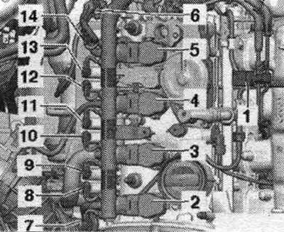
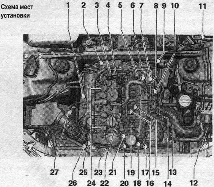
Overview of installation locations (CDNB, CDNC, CAEB, CDZA, CAEA and CADA)
Components A through I are not shown in the exploded view drawing.
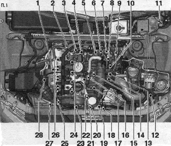
1. Lambda probe "G39" and lambda probe heating element "Z19".
2. Lambda probe after catalytic converter "G130" and heating element of lambda probe 1 after catalytic converter "Z29".
3. Fuel pressure regulator "N276".
4. High pressure pump.
5. Vacuum reservoir for charge air regulating flaps (intake manifold regulating flaps).
6. Intake manifold flap valve "N316".
7. Engine speed sensor "G28": 4.5 Nm.
8. Electromagnetic valve 1 of the activated carbon absorber "N80".
9. 6-pin plug connectors: for lambda probe "G39" and lambda probe heating element "Z19" (black); lambda probe after catalytic converter "G130" and lambda probe 1 heating after catalytic converter "Z29" (brown plug).
10. Plug connectors: for knock sensor 1 "G61", intake manifold flap valve "N316", fuel pressure sensor "G247", intake manifold flap potentiometer "G336", coolant temperature sensor "G62", Hall sensor "G40" and injectors N30...N33.
11. Engine control unit "J623".
12. Boost pressure sensor "G31".
13. Throttle control unit "J338", throttle actuator (electric throttle control) "G186"; throttle actuator angle sensor "G187" and throttle actuator angle sensor 2 "G188": after each removal and installation, or after replacing the throttle control unit "J338", it must be re-adapted to the engine control unit "J623".
14. Intake air temperature sensor "G42".
15. Knock sensor I "G61": to remove it, it is necessary to dismantle the coolant pump with thermostat; tightening torque: 20 Nm.
16. Coolant temperature sensor "G62".
17. Fuel pressure sensor "G247".
18. Oil pressure regulating valve "N428".
19. Oil pressure sensor for low pressure "F378".
20. Oil pressure sensor "F22".
21. Intake manifold flap potentiometer "G336".
22. Hall sensor "G40".
23. Valve 1 for adjusting the timing phases "N205".
24. Ignition coils with final stages: the coils should be removed from the cylinder head using the "T40039" puller.
25. Turbocharger bypass valve "N249": mounted directly on the turbocharger.
26. Actuating elements of valve timing control. Actuating element 1 of valve timing control "F366". Actuating element 2 of valve timing control "F367". Actuating element 3 of valve timing control "F368". Actuating element 4 of valve timing control "F369". Actuating element 5 of valve timing control "F370". Actuating element 6 of valve timing control "F371". Actuating element 7 of valve timing control "F372". Actuating element 8 of valve timing control "F373".
27. Electromagnetic boost pressure limitation valve "N75": installed directly on the turbocharger.
28. Air flow meter "G70".
A. Diagnostic connector: in the knee support on the driver's side.
B. Fuel control unit. pump "J538".
C. Brake light switch "F" and brake pedal switch "F47": in the footwell on the brake pedal.
D. Clutch pedal position sensor "G476": installed only on vehicles with manual transmission.
E. Accelerator pedal position sensor "G79" and accelerator pedal position sensor 2 "G185": on the accelerator pedal (both sensors are placed in one housing).
F. Radiator fan control unit "J293"; built into the radiator fan.
C. Injectors: Injector cyl. 1 "N30". Cyl. injector. 2 "N31". Cyl. injector. 3 "N32". Cyl. injector. 4 "N33".
H. Coolant forced circulation pump "V51": not installed on all vehicles (only very hot countries).
I. Left solenoid valve of electrohydraulic engine mount "N144": not installed on all vehicles (depending on the CP).
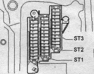
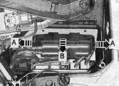
Engine control unit "J623"
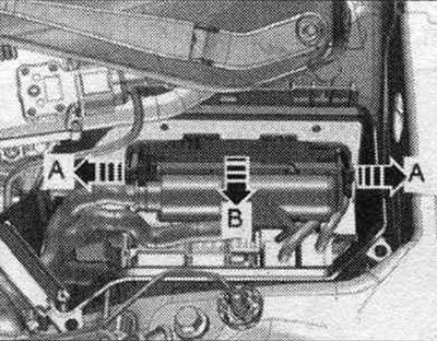
In the left switching unit of the motor. compartment.
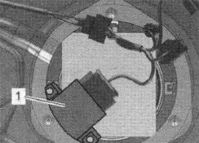
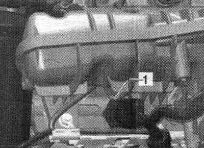
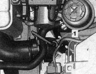
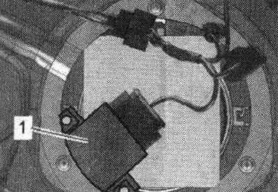
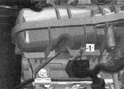
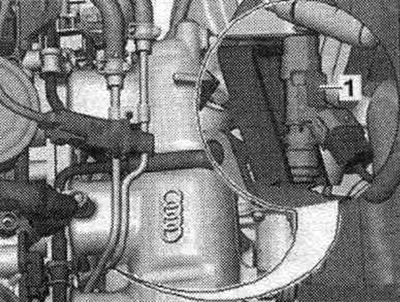
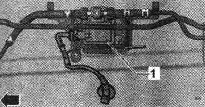
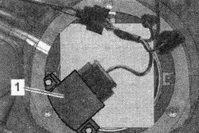
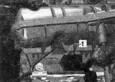
Fuel control unit. pump "J538" "1"
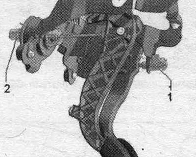
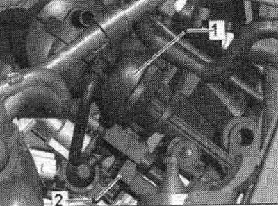
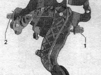
Accelerator pedal position sensor "G79" and accelerator pedal position sensor 2 "G185"
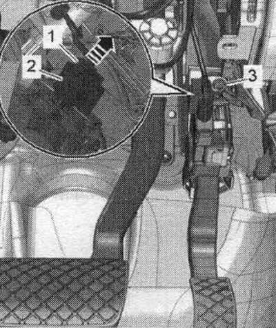
2. Plug connector.
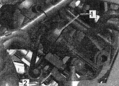
Clutch pedal position sensor "G476" "2"
Built-in functions: clutch pedal position sensor for engine starting "F194" and clutch pedal position sensor "F36" (only in vehicles with manual transmission).
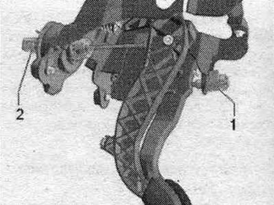
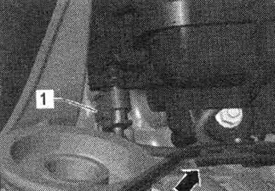
1. Brake light switch "F" and brake pedal sensor "F47"
Forced circulation pump for coolant "V51"
1. Electrical plug connector for coolant recovery pump "V51"
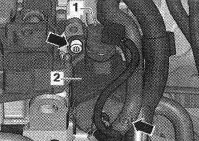
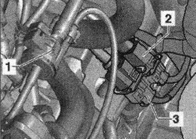
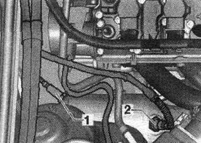
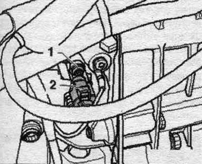
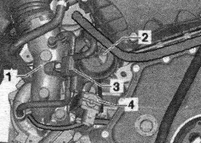
Oil pressure sensor
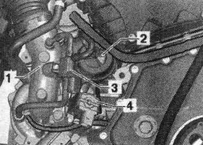
1. Electrical plug connector of the oil pressure sensor "F22"; 2. Oil pressure sensor "F22"; 3. Low pressure oil pressure sensor "F378"; 4. Electrical connector of oil pressure sensor for low pressure "F378".
Oil pressure regulating valve "N428" "3"
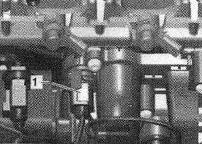
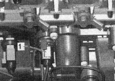
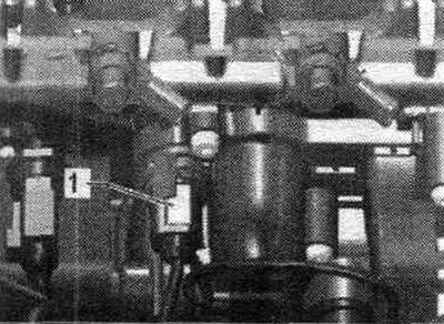
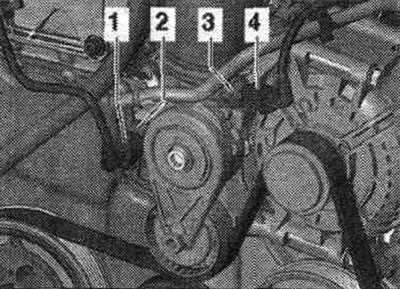
Coil
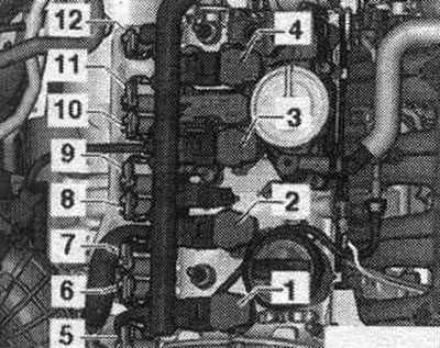
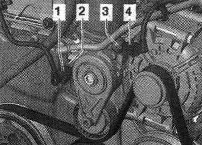
1. Coil 1 with output stage "N70"; 2. Coil 2 with output stage "N127"; 3. Coil 3 with output stage "N291"; 4. Coil 4 with output stage "N292"; 5. Actuator element 2 of the timing phase control "F367" (cyl. 1); 6. Executive element 1 of the timing phase control "F366" (cyl. 1); 7. Actuator element 3 of the timing phase control "F368" (cyl. 2); 8. Actuator element 4 of the timing phase control "F369" (cyl. 2); 9. Executive element 6 of the timing phase regulation "F371" (cyl. 3); 10. Executive element 5 of the timing phase control "F370" (cyl. 3); 11. Executive element 7 of the timing phase control "F372" (cyl. 4); 12. Executive element 8 for adjusting the timing phases "F373" (cyl. 4);
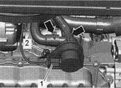
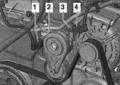
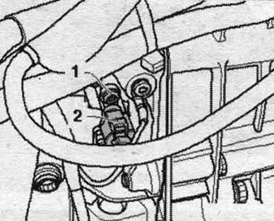
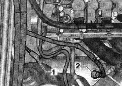
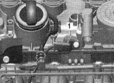
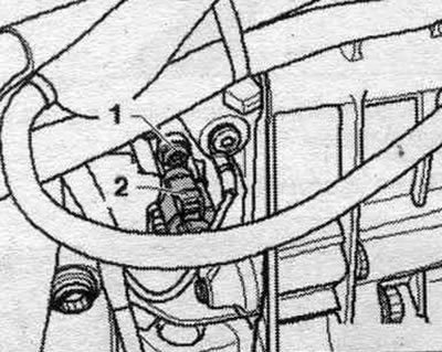
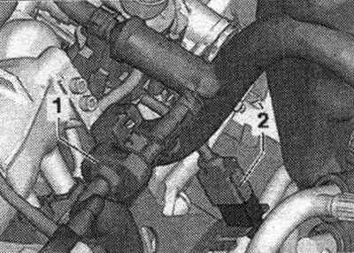
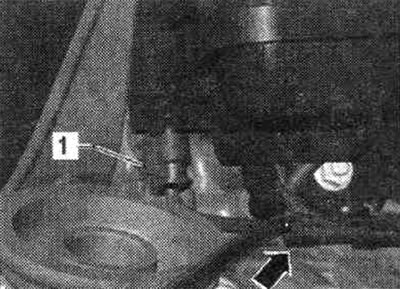
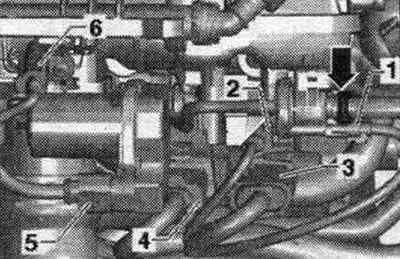
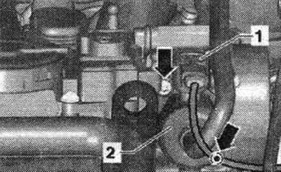
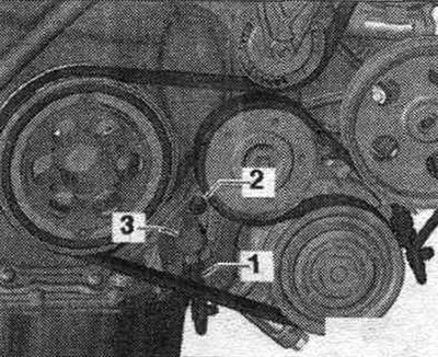
Fuel pressure sensor "G247" "1"
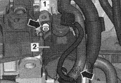
Intake manifold flap valve "N316" "2"
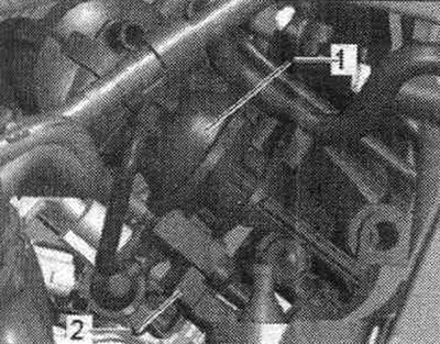
1. Vacuum reservoir for intake manifold flaps.
Intake manifold flap potentiometer "G336" "1"

Hall sensor "G40" "1"
Electrical plug connections
1. From the electromagnetic valve 1 of the absorber with activated carbon "N80"; 2. Knock sensor 1 "G61"; 3. (14-pin) intake manifold flap valve "N316", fuel pressure sensor "G247", intake manifold flap potentiometer "G336", coolant temperature sensor "G62" and Hall sensor "G40"; 4. (8-pin) injectors N30...N33; 5. From the throttle body "J338"; 6. From the intake air temperature sensor "G42".
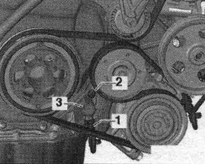
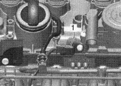
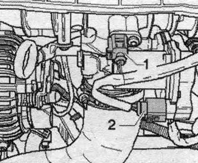
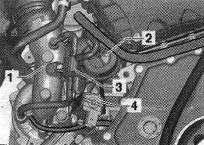
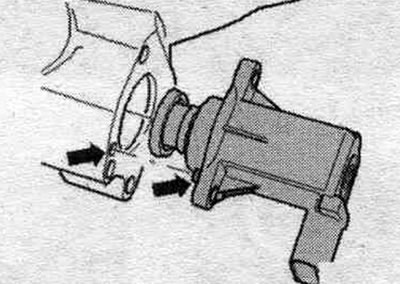
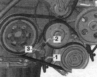
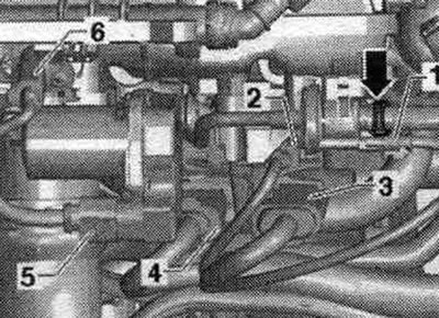
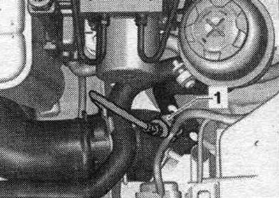
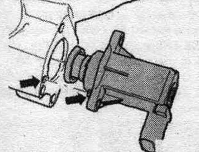
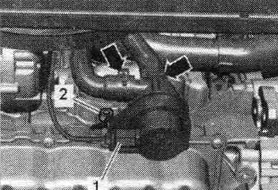
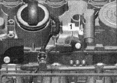
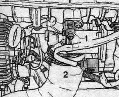
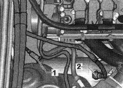
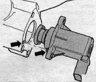
High pressure pump
1. Fuel pressure regulator "N276"; 2. High pressure pump; Arrow mounting bolts.
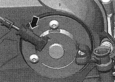
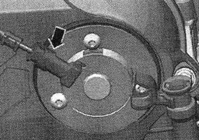
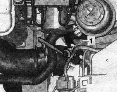
Engine speed sensor "028" "2"
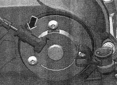
Valve 1 for adjusting the timing phases "N205" "arrow"
Details
1. Intake air temperature sensor "G42"; 2. Throttle control unit "J338".
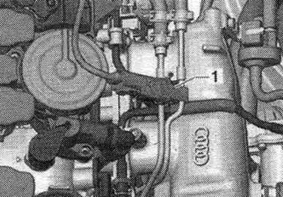
Coolant temperature sensor "062" "1"
Installation location under the intake manifold in the coolant pump.
Boost pressure sensor "G31" "1"
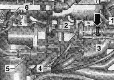
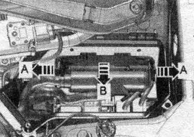
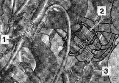
Node and plug connectors
1. Electromagnetic valve 1 of the activated carbon absorber "N80"; 2. Lambda probe after catalytic converter "G130" and heating element of lambda probe 1 after catalytic converter "Z29"; 3. Lambda probe "G39" and lambda probe heating element "Z19".
Lambda probes
1. Lambda probe after catalytic converter "G130" and heating element of lambda probe 1 after catalytic converter "Z29"; 2. Lambda probe "G39" and lambda probe heating element "Z19".
Components on a turbocharger
1. Turbocharger; 2. Turbocharger vacuum block, checking, adjustment, removal and installation; 3. Electromagnet. boost pressure limiting valve "N75"; 4. Turbocharger air bypass valve "N249" (observe installation. position, next figure)
Observe the installation position of the bypass air. turbocharger valve "N249"
Installation location diagram (CFKA, SRMA)
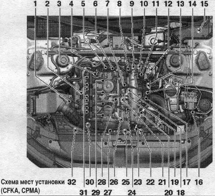
1. Air flow meter "G70".
2. Lambda probe "G39" and lambda probe heating element "Z19".
3. Electrical plug connection of the lambda probe "G39".
4. Lambda probe after catalytic converter "G130" and heating element of lambda probe 1 after catalytic converter "Z29".
5. Fuel pressure regulator "N276".
6. High pressure pump.
7. Low pressure fuel circuit pressure sensor "G410".
8. Vacuum reservoir for charge air regulating flaps (intake manifold regulating flaps).
9. Intake manifold flap valve "N316".
10. Engine speed sensor "G28": 4.5 Nm.
11. Electromagnetic valve 1 of the activated carbon absorber "N80".
12. 6-pin plug connector; lambda probe after catalytic converter "G130" and heating element of lambda probe 1 after catalytic converter "Z29".
13. Plug connectors: for knock sensor 1 "G61", intake manifold flap valve "N316", fuel pressure sensor "G247", intake manifold flap potentiometer "G336", coolant temperature sensor "G62", Hall sensor "G40" and injectors N30...N33.
14. Throttle control unit "J338", throttle actuator (electric throttle control) "G186": throttle valve drive angle sensor "G187" and throttle valve drive angle sensor 2 "G188"; after each removal and installation, or after replacing the throttle control unit "J338", it is necessary to re-adapt it to the engine control unit "J623".
15. Engine control unit "J623".
16. Boost pressure sensor "G31".
17. Vacuum connector on the intake manifold.
18. Starting injector "N17".
19. Knock sensor I "G61": to remove it, it is necessary to dismantle the coolant pump with thermostat; 20 Nm.
20. Intake air temperature sensor "G42".
21. Coolant temperature sensor "G62".
22. Oil pressure regulating valve "N428".
23. Oil pressure sensor for low pressure "F378".
24. Fuel pressure sensor "G247".
25. Oil pressure sensor "F22".
26. Intake manifold flap potentiometer "G336": when replacing the intake manifold, the intake manifold flap potentiometer "G336" must be re-adapted to the engine control unit "J623".
27. Valve 1 for adjusting the timing phases "N205".
28. Hall sensor "G40".
29. Ignition coils with final stages: the coils should be removed from the cylinder head using the "T40039" puller.
30. Turbocharger bypass valve "N249": mounted directly on the turbocharger.
31. Actuating elements of valve timing control: Actuating element 1 of valve timing control "F366". Actuating element 2 of valve timing control "F367". Actuating element 3 of valve timing control "F368". Actuating element 4 of valve timing control "F369". Actuating element 5 of valve timing control "F370". Actuating element 6 of valve timing control "F371". Actuating element 7 of valve timing control "F372". Actuating element 8 of valve timing control "F373".
32. Electromagnet. boost pressure limiting valve "N75": mounted directly on the turbocharger.
A. Fuel control unit. pump "J538".
B. Brake light switch "F" and brake pedal switch "F47": in the footwell on the brake pedal.
C. Clutch pedal position sensor "G476": installed only on vehicles with manual transmission.
D. Accelerator pedal position sensor "G79" and accelerator pedal position sensor 2 "G185": on the accelerator pedal (both sensors are placed in one housing).
E. Radiator fan control unit "J293": integrated into the radiator fan.
F. Injectors: Injector cyl. 1 "N30". Cyl. injector. 2 "N31". Cyl. injector. 3 "N32". Cyl. injector. 4 "N33": these are high-pressure injectors, they inject fuel under high pressure (maximum, up to approximately 120 bar) directly into the cylinder.
G. Coolant forced circulation pump "V51": not installed on all vehicles (very hot countries).
N. Left solenoid valve of electrohydraulic engine mount "N144": not installed on all vehicles (depending on the CP).
I. Fuel quality sensor "G446".
Engine control unit "J623"
Fuel control unit. pump "J538" "1"
Accelerator pedal position sensor "G79" and accelerator pedal position sensor 2 "G185"
Clutch pedal position sensor "G476" "2"
Built-in functions: clutch pedal position sensor for engine starting "F194" and clutch pedal position sensor "F36" (only in vehicles with manual transmission).
1. Brake light switch "F" and brake pedal sensor "F47".
Oil pressure sensor
1. Electrical plug connector of the oil pressure sensor "F22"; 2. Oil pressure sensor "F22"; 3. Low pressure oil pressure sensor "F378"; 4. Electrical connector of oil pressure sensor for low pressure "F378".
Oil pressure regulating valve "N428" "3"
Ignition coils and actuators
1. Low-pressure fuel pressure sensor "G410"; 2. Coil 1 with output stage "N70"; 3. Coil 2 with output stage "N127"; 4. Coil 3 with output stage "N291"; 5. Coil 4 with output stage "N292"; 6. Plug connection of the lambda probe "G39"; 7. Actuator element 2 for adjusting the timing phases "F367" (cyl. 1); 8. Actuator element 1 of the timing phase control "F366" (cyl. 1); 9. Actuator element 3 of the timing phase control "F368" (cyl. 2); 10. Actuator element 4 of the timing phase control "F369" (cyl. 2); 11. Executive element 6 of the timing phase control "F371" (cyl. 3); 12. Executive element 5 of the timing phase control "F370" (cyl. 3); 13. Executive element 7 for adjusting the timing phases "F372" (cyl. 4); 14. Executive element 8 for adjusting the timing phases "F373" (cyl. 4).
Fuel pressure sensor "C247" "1"
Intake manifold flap valve "N316" "2"
1. Vacuum reservoir for intake manifold flaps.
Intake manifold flap potentiometer "G336" "1"
Hall sensor "G40" "1"
Electrical plug connections
1. From the electromagnetic valve 1 of the absorber with activated carbon "N80"; 2. Knock sensor 1 "G61"; 3. (14-pin) intake manifold flap valve "N316", fuel pressure sensor "G247", intake manifold flap potentiometer "G336", coolant temperature sensor "G62" and Hall sensor "G40"; 4. (8-pin) injectors N30...No.33; 5. From the throttle body "J338"; 6. From the intake air temperature sensor "G42".
High pressure pump
1. Fuel pressure regulator "N276"; 2. Fuel injection pump; Arrow mounting bolts.
Low Pressure Fuel Pressure Sensor "G410" "1"
Engine speed sensor "G28" "2"
Valve 1 for adjusting the timing phases "N205" "arrow"
Coolant temperature sensor "G62" "1"
The installation location is under the intake manifold in the coolant pump.
Boost pressure sensor "G31" "1"
Starting injector "N17" "1"
Node and plug connectors
1. Electromagnetic valve 1 of the activated carbon absorber "N80"; 2. Lambda probe after catalytic converter "G130" and heating element of lambda probe 1 after catalytic converter "Z29".
Lambda probes
1. Lambda probe after catalytic converter "G130" and heating element of lambda probe 1 after catalytic converter "Z29"; 2. Lambda probe "G39" and lambda probe heating element "Z19".
Components on a turbocharger
1. Turbocharger; 2. Turbocharger vacuum block, checking, adjustment, removal and installation; 3. Electromagnetic boost pressure limiting valve "N75"; 4. Turbocharger air bypass valve "N249" (observe installation. position, next figure).
Observe the installation position of the bypass air. turbocharger valve "N249"
Fuel quality sensor "G446" "1"
The installation location of the fuel quality sensor "G446" is on the bottom on the right (the arrow indicates the direction of movement).
Installation location diagram
Components A through I are not shown in the exploded view drawing.
1. Lambda probe "G39" and lambda probe heating element "Z19".
2. Lambda probe after catalytic converter "G130" and heating element of lambda probe 1 after catalytic converter "Z29".
3. Fuel pressure regulator "N276".
4. Fuel injection pump.
5. Vacuum reservoir for charge air regulating flaps (intake manifold regulating flaps).
6. Intake manifold flap valve "N316".
7. Engine speed sensor "G28": 4.5 Nm.
8. Electromagnetic valve 1 of the activated carbon absorber "N80".
9. 6-pin plug connectors: for lambda probe "G39" and lambda probe heating element "Z19" (black); lambda probe after catalytic converter "G130" and lambda probe 1 heating after catalytic converter "Z29" (brown plug).
10. Plug connectors for: knock sensor 1 "G61", intake manifold flap valve "N316", fuel pressure sensor "G247", intake manifold flap potentiometer "G336", coolant temperature sensor "G62", Hall sensor "G40", injectors N30...N33.
11. Engine control unit "J623".
12. Boost pressure sensor "G31".
13. Throttle control unit "J338", throttle actuator (electric throttle control) "G186": throttle valve drive angle sensor "G187" and throttle valve drive angle sensor 2 "G188"; after each removal and installation, or after replacing the throttle control unit "J338", it is necessary to re-adapt it to the engine control unit "J623".
14. Intake air temperature sensor "G42".
15. Knock sensor I -G61-: to remove it, it is necessary to dismantle the coolant pump with thermostat; 20 Nm.
16. Coolant temperature sensor "G62".
17. Oil pressure regulating valve "N428".
18. Oil pressure sensor for low pressure "F378".
19. Fuel pressure sensor "G247".
20. Oil pressure sensor "F22".
21. Intake manifold flap potentiometer "G336".
22. Hall sensor "G40" (camshaft position sensor).
23. Valve 1 for adjusting the timing phases "N205".
24. Ignition coils with final stages: the coils should be removed from the cylinder head using the "T40039" puller.
25. Turbocharger bypass valve "N249": mounted directly on the turbocharger.
26. Electromagnetic boost pressure limiting valve "N75": installed directly on the turbocharger.
27. Air flow meter "G70".
A. Diagnostic connector: in the knee support on the driver's side.
B. Fuel control unit. pump "J538".
C. Brake light switch "F" and brake pedal switch "F47": in the footwell on the brake pedal.
D. Clutch pedal position sensor "G476": installed only on vehicles with manual transmission.
E. Accelerator pedal position sensor "G79" and accelerator pedal position sensor 2 "G185": on the accelerator pedal (both sensors are placed in one housing).
F. Radiator fan control unit "J293": integrated into the radiator fan.
G. Injectors: in the fuel rail. Injector cyl. 1 "N30". Cyl. injector. 2 "N31". Cyl. injector. 3 "N32". Cyl. injector. 4 "N33".
H. Coolant forced circulation pump "V51": only for countries with hot climates.
I. Left solenoid valve of electrohydraulic engine mount "N144": not installed on all vehicles (depending on the CP).
Engine control unit "J623"
In the left switching unit of the motor. compartment.
Fuel control unit. pump "J538" "1"
Accelerator pedal position sensor "G79" and accelerator pedal position sensor 2 "G185"
2. Plug connector.
Clutch pedal position sensor "G476" "2"
Built-in functions: clutch pedal position sensor for engine starting "F194" and clutch pedal position sensor "F36" (only in vehicles with manual transmission).
1. Brake light switch "F" and brake pedal sensor "F47".
Forced circulation pump for coolant "V51"

1. Electrical plug connector for coolant recovery pump "V51".
Coil
1. Coil 1 with output stage "N70"; 2. Coil 2 with output stage "N127"; 3. Coil 3 with output stage "N291"; 4. Coil 4 with output stage "N292".
Fuel pressure sensor "G247" "1"
The tightening torque of the pipes "25 Nm" must be checked before installing the fuel pressure sensor "G247".
Intake manifold flap valve "N316" "2"
1. Vacuum reservoir for intake manifold flaps.
Intake manifold flap potentiometer "G336" "1"
Hall sensor "G40" "1"
Electrical connectors
1. Dt el. magnetic valve 1 of the absorber with activated carbon "N80"; 2. Knock sensor 1 "G61"; 3. (14-pin connector) intake manifold flap valve "N316", fuel pressure sensor "G247", intake manifold flap potentiometer "G336", coolant temperature sensor "G62" and Hall sensor "G40"; 4. (8-pin) injectors N30...N33; 5. From the throttle body "J338"; 6. From the intake air temperature sensor "G42".
fuel injection pump
1. Fuel pressure regulator "N276"; 2. Fuel injection pump; Arrow mounting bolts.
Engine speed sensor "G28" "2"
Valve 1 for adjusting the timing phases "N205" "arrow"
Details
1. Intake air temperature sensor "G42"; 2. Throttle control unit "J338".
Coolant temperature sensor "G62" "1"
Boost pressure sensor "G31" "1"
Oil pressure sensor
2. Oil pressure sensor "F22"; 3. Oil pressure sensor for low pressure "F378".
Oil pressure regulating valve "N428" "3"
Node and plug connectors
1. Electromagnetic valve 1 of the activated carbon absorber "N80"; 2. Lambda probe after catalytic converter "G130" and heating element of lambda probe 1 after catalytic converter "Z29"; 3. Lambda probe "G39" and lambda probe heating element "Z19".
Lambda probes
1. Lambda probe after catalytic converter "G130" and heating element of lambda probe 1 after catalytic converter "Z29"; 2. Lambda probe "G39" and lambda probe heating element "Z19".
Components on a turbocharger
1. Turbocharger; 2. Turbocharger vacuum block, checking, adjustment, removal and installation; 3. Electromagnetic boost pressure limiting valve "N75"; 4. Turbocharger air bypass valve "N249" (observe installation. position, next figure).
Observe the installation position of the bypass air. turbocharger valve "N249"
Information obtained from this resource audimanual.ru