Repair Chevrolet Repair Toyota Repair Honda Repair AvtoVAZ Repair Mercedes-Benz Repair BMW Repair Opel
Home  |  Contacts  |  Sitemap  |    
English Русский
Български
Беларускі
Український
Српски
Hrvatski
Română
Polski
Slovenský
Magyar
AudiManual.ru


  • AUDI 80
  • AUDI 100
  • AUDI A3
  • AUDI A4
  • AUDI A6
  • AUDI A8
  • AUDI Q
  • OTHER
  • ARTICLES
B8 (2007-2015) B7 (2004-2008) B6 (2000-2006) B6 (2000-2006, petrol) B5 (1994-2001) B5 (1994-2001, petrol)

Intake manifold (CFKA, SRMA) — removal and installation (Audi A4 B8)

  • Home
  • Audi A4
  • B8 (2007-2015)
  • Power unit
  • Petrol engines 1.8/2.0 l
  • Intake manifold (CFKA, SRMA) — removal and installation
            0
Table of contents: Fuel rail ↓ Removal and installation the upper… ↓ Removal and installation the lower… ↓ Removal and installation of the cold… ↓
Intake manifold (CFKA, SRMA)

1. Intake air temperature sensor bolt «G42»: 9 Nm.

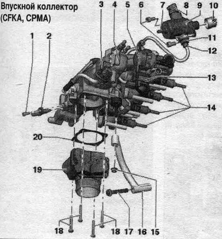
1. Intake air temperature sensor bolt "G42": 9 Nm.
2. Intake air temperature sensor "G42".
3. Electromagnetic valve 1 of the activated carbon absorber "N80".
4. Intake manifold: tighten to a torque of 9 Nm.
5. Vacuum reservoir for charge air regulating flaps (intake manifold regulating flaps).
6. High pressure pump bolts: tighten crosswise to 5 Nm and then tighten to 20 Nm.
7. The connection for the fuel supply line coming from the tank.
8. Fuel pressure regulator "N276".
9. High pressure pump: with fuel pressure regulating valve "N276"; there is an electric heater in the fuel tank. fuel pump, which supplies fuel to the mechanics. high-pressure pump; when installing a high pressure pump, it is necessary to ensure that the fuel. no dirt got into the system; before installing the high pressure fuel pump. the system should not be under pressure, relieve the pressure; install fuel lines without distortions.
10. Roller tappet: can remain inserted after removing the injection pump in the vacuum pump, removable.
11. Fuel supply line nipple: not a spare part, but a component of the high-pressure pump; do not weaken; depending on the design, an adapter is installed between the connecting nipple and the fuel supply. highway; if the adapter is installed, it should be replaced; 40 Nm.
12. Fuel supply union nut. highways: Install fuel lines without distortions; 20 Nm.
13. Intake manifold flap valve "N316".
14. Injectors: replace the seal. and Teflon rings, take into account the installation. position.
15. Fastening nut for intake manifold pipe: 10 Nm.
16. Intake manifold support.
17. Intake manifold pipe bolt: 23 Nm.
18. Throttle body bolts "J338": 10 Nm.
19. Throttle valve control unit "J338", throttle valve drive "G186", throttle valve drive angle sensor 1 "G187" and throttle valve drive angle sensor 2 "G188": After replacing the throttle valve control module "J338", it must be re-aligned with the engine control unit "J623", use the tester for this.
20. Gasket: replace.


Clamp


Tightening torque: 10 Nm.

Tightening torque: 10 Nm.


Starting injector "N17"


Tightening torque: 10 Nm.

Tightening torque: 10 Nm.


Fuel rail


1. Injector: always replace together with the combustion chamber seal (Teflon seal. ring); replace…

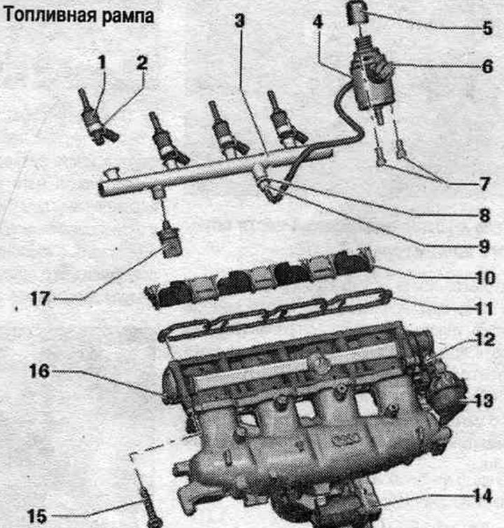
1. Injector: always replace together with the combustion chamber seal (Teflon seal. ring); replace the seal. rings, take into account installation. position.
2. Support ring.
3. Fuel rail: 10 Nm.
4. High pressure pump: with fuel pressure regulating valve "N276"; there is an electric heater in the fuel tank. fuel pump, which supplies fuel to the mechanics. high-pressure pump; when installing a high pressure pump, it is necessary to ensure that the fuel. no dirt got into the system; before installing the high pressure fuel pump. the system should not be under pressure, relieve the pressure; install fuel lines without distortions.
5. Roller pusher.
6. Fuel pressure regulator "N276".
7. High pressure pump bolts: tighten crosswise to 5 Nm and then tighten to 20 Nm.
8. Fuel supply nipple. highways to fuel. ramp: replace, 40 Nm.
9. Fuel supply union nut. highway: 20 Nm.
10. Compression valves (intake manifold flaps).
11. Gasket: replace.
12. Intake manifold.
13. Vacuum reservoir for charge air regulating flaps.
14. Throttle valve control unit "J338", throttle valve drive "G186", throttle valve drive angle sensor 1 "G187" and throttle valve drive angle sensor 2 "G188"; after each removal and installation, or after replacing the throttle control unit "J338", it is necessary to re-adapt it to the engine control unit "J623"; 7 Nm.
15. Intake manifold bolts: 9 Nm.
16. Intake manifold flap potentiometer "G336": when replacing the intake manifold flap potentiometer "G336", it is necessary to adapt the intake manifold flap potentiometer "G336" to the engine control unit "J623"; after each removal and installation of the intake manifold flap potentiometer "G336" or the intake manifold, it is necessary to adapt the intake manifold flap potentiometer "G336" to the engine control unit "J623" using an automotive tester.
17. Fuel pressure sensor "G247": 27 Nm; lubricate the threads with clean oil; always replace the nipple and tighten to 40 Nm.


Starting injector "N17" "1"


Starting injector «N17» «1»


Removal and installation the upper part of the intake manifold


To access the injectors, you need to remove the intake manifold from the fuel. ramp. Replace the combustion chamber seal (Teflon) and O-ring. The fuel in the fuel system is under pressure! Disconnect the (-) terminal from the battery. Remove the engine cover. Disconnect the vacuum line "arrow" to the activated carbon absorber. Disconnect the following connectors.

1. Electromagnetic valve 1 of the activated carbon absorber «N80»; 2. Knock sensor 1 «G61»; 3. From…

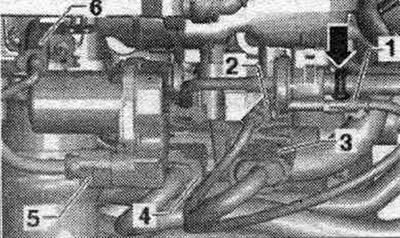
1. Electromagnetic valve 1 of the activated carbon absorber "N80"; 2. Knock sensor 1 "G61"; 3. From the intake manifold flap valve "N316", fuel pressure sensor "G247" and Hall sensor "G40"; 4. From the injectors; 5. Throttle control unit "J338"; 6. Intake air temperature sensor "G42".


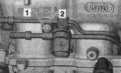
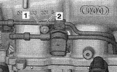
Unscrew bolts "1 and 2" and remove the bracket for electrical connectors.

Unscrew bolts «1 and 2» and remove the bracket for electrical connectors.


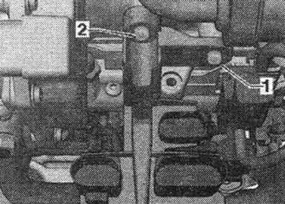
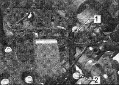
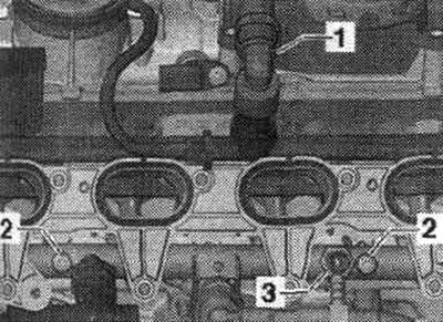
Disconnect the electrical. connector "2" from the low-pressure fuel pressure sensor "G410." Disconnect connector "4" from the Hall sensor "G40." Open clamps "1" and remove both fuel lines. Remove clamp "3".

Disconnect the electrical. connector «2» from the low-pressure fuel pressure sensor «G410.»…


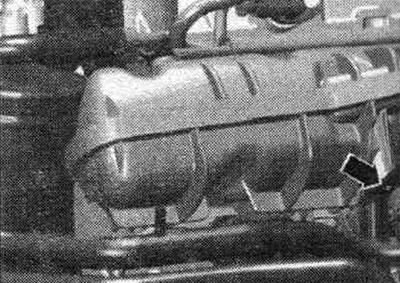
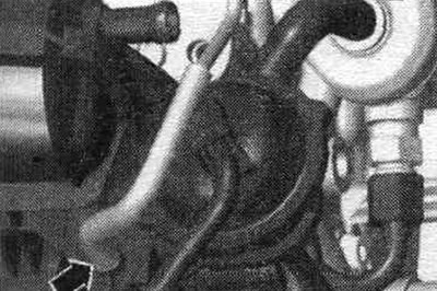
Disconnect the activated carbon line from the top of the intake manifold and remove the "arrows" at the disconnection point. Remove the el. magnetic valve 1 of the activated carbon absorber "N80" "5". Remove the activated carbon line under the fuel lines and set it aside. Open the clamp "arrow" of the air duct hose and disconnect the hose from the throttle valve module "J338" downwards.

Disconnect the activated carbon line from the top of the intake manifold and remove the «arrows» at…


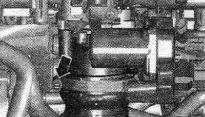
Open the fuel cap union nut. high-pressure lines - bottom arrow - on the fuel injection pump. Unscrew the union nuts and remove the high-pressure fuel line. Open the union nut of the high pressure fuel line on the fuel. ramp.


Open the fuel cap union nut. high-pressure lines - bottom arrow - on the fuel injection pump.…


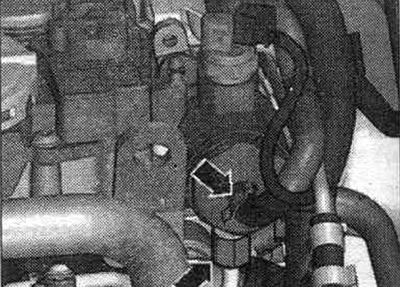
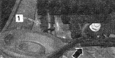
Remove the coolant line bolt "arrow" from the top of the intake manifold.

Remove the coolant line bolt «arrow» from the top of the intake manifold.


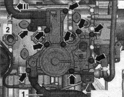
Remove screw "2". Loosen the bolts using the "T10347" socket on the wrench from the top of the intake manifold. Disconnect the upper intake manifold from the lower intake manifold.

Remove screw «2». Loosen the bolts using the «T10347» socket on the wrench from the top of the…


Remove the N17 starting injector connector. Cover the intake ports with a clean rag. Remove the lower part of the intake manifold.


Remove the N17 starting injector connector. Cover the intake ports with a clean rag. Remove the…


Install


Replace the high-pressure fuel line connector on the injection pump and fuel rail. Install the intake manifold using the mounting pins (left and right below) onto the cylinder head. Hand-tighten the high-pressure fuel line union nuts. Tighten the intake manifold to torque (Tighten the bolts from the inside out). Tighten the high pressure fuel line to the specified torque. Installation in reverse order.

Removal and installation the lower part of the intake manifold


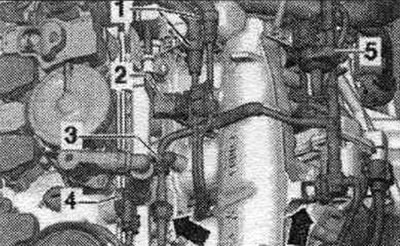
When removing or replacing the lower section of the intake manifold, it is necessary to re-adapt the intake manifold valve potentiometer "G336" to the engine control unit "J623". Remove the upper section of the intake manifold. Remove the vacuum line "arrow" from the intake manifold flap valve "N316". Remove the intake manifold flap valve "N316" from the holder.

When removing or replacing the lower section of the intake manifold, it is necessary to re-adapt…


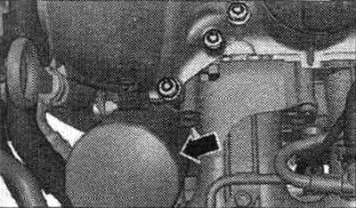
Loosen the oil filter "arrow" using the key "3417" and remove it.


Loosen the oil filter «arrow» using the key «3417» and remove it.


Loosen the crankcase ventilation "arrow" bolts by several thread turns.

Loosen the crankcase ventilation «arrow» bolts by several thread turns.


Disconnect the engine crankcase ventilation hose "1". Unscrew the connecting nipple "3". Remove the lower part of the intake manifold.

Disconnect the engine crankcase ventilation hose «1». Unscrew the connecting nipple «3». Remove the…


Disconnect electrical connector "1" from the intake manifold flap potentiometer "G336".

Disconnect electrical connector «1» from the intake manifold flap potentiometer «G336».


Install


Ensure that the injectors are installed correctly. Always replace both fuel supply line fittings. Reconnect the plug connection of the intake manifold flap potentiometer "G336". Install the intake manifold. Installation in reverse order.


Removal and installation of the cold start injector "N17"


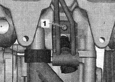
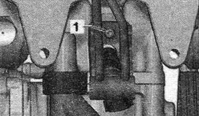
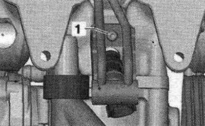
Remove the intake manifold. Unscrew bolt "1" of clamp "2" on the intake manifold.

Remove the intake manifold. Unscrew bolt «1» of clamp «2» on the intake manifold.


Unscrew bolt "1" of the starting injector "N17". Remove the starting injector "N17" with the fastener from the hole.

Unscrew bolt «1» of the starting injector «N17». Remove the starting injector «N17» with the…


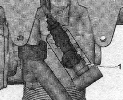
Remove clamp "1". Carefully remove the starting injector "N17" from the mount.

Remove clamp «1». Carefully remove the starting injector «N17» from the mount.


Install


Installation in reverse order. Install the intake manifold.

This publication is borrowed from the resource: AudiManual.ru
The article was checked by auto expert Timur Bazhenov
This article is available at russian, bulgarian, belarusian, ukrainian, serbian, croatian, romanian, polish, slovak, hungarian

Share information:
Previous articles
Audi A4 B8: Petrol engines 1.8/2.0 l
Next articles

Intake manifold (CDNB, CDNC, SAEV, CDZA, SAEA, CADA) — removal…
Air filter — removal and installation
Fuel injection system
Turbocharger — removal and installation
High-pressure pump, injectors and lambda probes — removal and…
Exhaust system (EG) — removal and installation
Ignition system — removal and installation of components


Similar articles on other Audi car models:
Intake manifold — removal and installation Audi 80 B3 (1986-1991, petrol)
Intake manifold — removal and installation Audi 100 C3 (1982-1990, diesel)
Removal and installation the lower engine compartment cover Audi A3 Type 8L (1996-2003)
Intake manifold — removal and installation Audi A6 C5 Allroad (1999-2005)
Removal and installation the engine Audi A8 D2 (1994-2002)
Removal and installation of the intake manifold and its… Audi Q7 Typ 4L (2005-2015, diesel)
Removal and installation the intake manifold Audi A2 (1999-2005)
Link to this page in different formats


Visitor comments

No comments yet


How much will 36 + 11 =


A4(B8, 2007-2015) 
  • General information
  • Operating instructions
  • Power unit
  • Petrol engines 1.8 l
  • Petrol engines 1.8/2.0 l
  • Petrol engines 3.0 l
  • Petrol engines 3.2 l
  • Fuel system (petrol)
  • Diesel engines 2.0 l (CA*)
  • Diesel engines 2.0 l (CJCB)
  • Diesel engines 2.7/3.0 l
  • Diesel engines 3.0 l
  • Fuel system (diesel)
  • Transmission
  • Manual gearbox 0B1
  • Manual gearbox 0B2
  • Manual gearbox 0B3
  • Manual gearbox 0B4
  • Automatic transmission 0B5
  • Automatic transmission 0B6
  • Automatic transmission 0AW
  • All-wheel drive system
  • Chassis
  • Front suspension
  • Rear suspension
  • Brake system
  • Steering system
  • Body
  • Exterior
  • Interior
  • Seats
  • Doors, locks and windows
  • Security system
  • Heating and air conditioning
  • Electrical equipment
  • Audio system
  • Power devices
  • Equipment and devices
  • Lighting and lamps
  • Electrical circuits
 
A4(B7, 2004-2008) 
  • General information
  • Introduction to manual
  • Troubleshooting
  • Operating instructions
  • Maintenance
  • Power unit
  • Petrol engines 2.0 (ALT)
  • Petrol engines 2.0 (TFSI)
  • Petrol engines 1.8 (MPI)
  • Diesel engines
  • Cooling system
  • Air conditioner
  • Fuel and exhaust system
  • Ignition system
  • Starting and charging
  • Transmission
  • Clutch
  • Manual gearbox
  • Automatic gearbox
  • Drive shafts
  • Chassis
  • Brake system
  • Front suspension
  • Rear suspension
  • Steering
  • Body
  • Exterior
  • Interior
  • Electrical equipment
  • Equipment and devices
  • Lighting and signaling
  • Windscreen wipers and washers
  • Electrical diagrams
  • Electrical diagrams (since 2007)
 
A4(B6, 2000-2006) 
  • General information
  • Vehicle Description
  • User manual
  • Maintenance
  • Power unit
  • Gasoline engine
  • Diesel engine
  • Lubrication system
  • Cooling system
  • Supply system
  • Injection system
  • Exhaust system
  • Ignition and control
  • Transmission
  • Gear box
  • Clutch and drive shafts
  • Chassis
  • Brake system
  • Car suspension
  • Steering
  • Body
  • Heating and ventilation
  • Exterior (external elements)
  • Interior (internal elements)
  • Electrical equipment
  • Power devices
  • Lighting and appliances
  • Electrical circuits
 
A4(B6, 2000-2006, petrol) 
  • General information
  • Introduction to the guide
  • Car care
  • Power unit
  • Engine repair
  • Lubrication system
  • Cooling system
  • Injection and control system
  • Ignition system
  • Power and exhaust system
  • Transmission
  • Clutch and drive shafts
  • Car gearbox
  • Chassis
  • Suspension and wheels
  • Steering
  • Brake system
  • Body
  • Interior
  • Exterior
  • Electrical equipment
  • Equipment and devices
  • Lighting and signaling
  • Power devices
  • Electrical circuits
 
A4(B5, 1994-2001) 
  • General information
  • Introduction to the guide
  • Car care
  • Maintenance (gasoline)
  • Maintenance (diesel)
  • Power unit
  • Gasoline engines
  • Diesel engines
  • Engine overhaul
  • Cooling system
  • Fuel injection (gasoline)
  • Fuel system (diesel)
  • Exhaust system
  • Ignition system
  • Transmission
  • Clutch
  • Mechanical gearbox
  • Automatic gearbox
  • Drive shafts
  • Chassis
  • Brake system
  • Car suspension
  • Steering
  • Body
  • Exterior
  • Interior
  • Doors, locks and windows
  • Heating and ventilation
  • Electrical equipment
  • Power devices
  • Equipment and devices
  • Electrical circuits
 
A4(B5, 1994-2001, petrol) 
  • General information
  • Vehicle description
  • Maintenance
  • Power unit
  • Engine repair
  • Turbocharging
  • Exhaust system
  • Cooling system
  • Ignition system
  • Fuel system
  • Motronic injection system
  • MPI and MPFI injection system
  • Transmission
  • Clutch
  • Gearbox and shafts
  • Chassis
  • Steering
  • Car suspension
  • Brake system
  • Wheels and tires
  • Body
  • Heating and ventilation
  • Body parts
  • Electrical equipment
  • Fuses and relays
  • Power devices
  • Lighting and lamps
  • Tools and devices
  • Electrical circuits
 
AudiManual.ru © 2017-2026 · Mobile version · Feedback · Sitemap: EN BG BY UA RS HR RO PL SK HU · Site search · News and articles
80 B2 · 80 B3 petrol · 80 B3 · 80 B4 · 100 C3 diesel · 100 C3 petrol · 100 C3 · 100 C4 petrol · 100 C4 · A3 Type 8L · A4 B5 petrol · A4 B5 · A4 B6 petrol · A4 B6 · A4 B7 · A4 B8 · A6 C4 · A6 C5 · A6 C5 Allroad · A8 D2 · Q5 Type 8R · Q7 Typ 4L · Audi A2 ·
This site uses cookies 🍪. Click the button to accept this fact.