
Table of contents: High pressure pump ↓ Removal and installation injectors ↓ Nozzle (old version) ↓ Nozzle (new version) ↓ Lambda probes ↓ Electrical connections of lambda… ↓ CFKA and CPMA ↓
High pressure pump
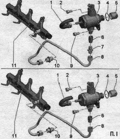
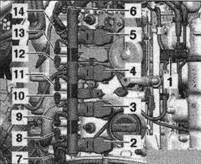
1. Fuel supply. main line from fuel. tank.
2. High pressure pump bolt: tighten crosswise to 5 Nm and then tighten to 20 Nm, avoid distortion of the high pressure pump.
3. High pressure pump: there is an electric pump in the fuel tank. fuel pump, which supplies fuel to the mechanics. high-pressure pump; when installing a high pressure pump, it is necessary to ensure that the fuel. system. no dirt gets in: before installing the high pressure fuel pump. the system should not be under pressure, relieve the pressure; install fuel lines without distortions.
4. Sealing ring: replace.
5. Roller tappet: Sometimes remains in the vacuum pump after the high pressure pump is removed.
6. Connecting pipe: not a spare part, an integral part of the high pressure pump, do not loosen.
7. Adapter: Depending on the design, an adapter is installed between the connecting nipple and the fuel supply. highway; if the adapter is installed, it should be replaced; 40 Nm.
8. High-pressure fuel line: install the fuel line without distortions; 20 Nm.
9. High pressure pump bolt: tighten crosswise to 5 Nm and then tighten to 20 Nm, avoid distortion of the high pressure pump.
10. Fuel supply nipple. highways to fuel. ramp: replace; 40 Nm.
11. Fuel rail.
Note: Remove the high pressure pump only when the engine is cold. When installing a high pressure pump, it is necessary to ensure that there is no fuel in the fuel. no dirt got into the system. Collect leaking fuel with a rag. Always replace the sealing ring. High pressure fuel lines must always be secured so that they are free from internal mechanical stress.
Take off
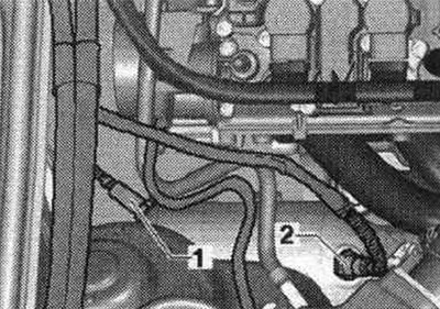
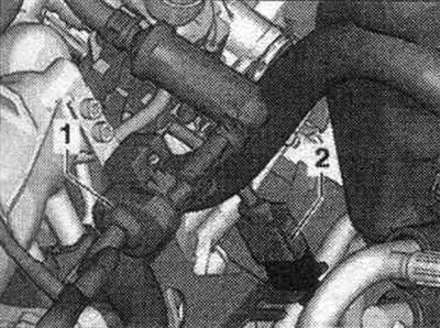
Remove the engine cover. Disconnect electrical connector "1" from fuel pressure regulating valve "N276".
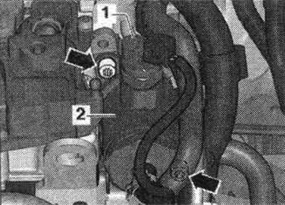
Disconnect both fuel lines. highway "arrows".
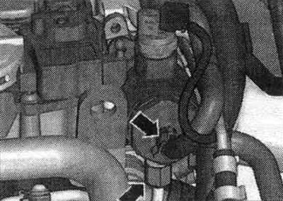
Unscrew the 2 "arrow" screws. Carefully remove the fuel tank. high pressure pump. The roller tappet sometimes remains in the vacuum pump.
Install
Replace the seal. high pressure pump ring. Install the roller tappet into the vacuum pump (pre-check the roller follower for damage). To install the fuel injection pump, the roller tappet must be in the lowest position. When installing the same or a used fuel injection pump, it is necessary to replace the fuel supply connection nipple. highways (high pressure side). Turn the cardan shaft so that the roller tappet is in its lowest position. Install the fuel injection pump into the vacuum pump and secure it. Tighten the bolts by hand. Replace the high pressure pump connection nipple. Now tighten all bolts crosswise to the specified tightening torque. Tighten the fuel supply line union nut by hand. Align without distortion or tension. Reconnect connector "1" of the fuel pressure regulating valve "N276". If the fuse was removed, reinstall it. Check fuel. system for leaks.
Removal and installation injectors
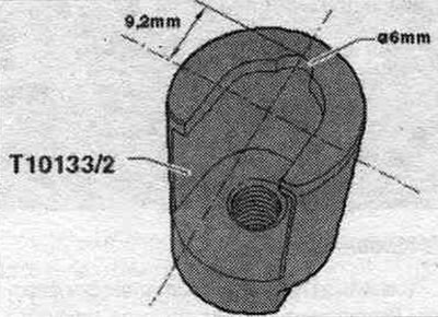
Note: Tool: puller T10133/2 has been changed and the new name is puller T10133/2 A. If you do not have this tool, you can change the old tool yourself.
Converting the T10133/2 puller into the T10133/2A puller
Cut out a semicircle as shown in the picture. The semicircle allows the tool to be placed deeper onto the nozzle, which provides a larger contact surface for the tool. At the end of the number of the converted tool, the letter "A" should be written.
Take off
Remove the engine cover. Remove the intake manifold and fuel. ramp. Remove the injectors if they remain in the fuel tank. Ramp. Carefully remove the injectors from the fuel. ramps. Remove the injectors if they remain in the cylinder head.
Nozzle (old version)
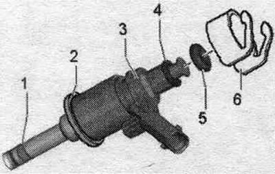
1. Combustion chamber seal (Teflon seal. ring) replace; it is not permissible for the ring to be covered with grease or any other lubricant during installation.
2. The support ring is replaced with an intermediate one. See the next figure - Fig.
3. Nozzle.
4. Spacer ring (replace if damaged).
5. Sealing ring (replace, lightly lubricate with clean oil when installing).
6. Support ring (through this support ring fuel. the ramp transmits the force that holds the injector in the cylinder head).
Nozzle (new version)
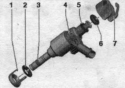
1. Replace the intermediate ring.
2. Emphasis.
3. Combustion chamber seal (Teflon seal. ring) replace; it is not permissible for the ring to be covered with grease or any other lubricant during installation.
4. Nozzle.
5. Spacer ring (replace if damaged).
6. Sealing ring (replace, lightly lubricate with clean oil when installing).
7. Support ring (through this support ring fuel. the ramp transmits the force that holds the injector in the cylinder head).
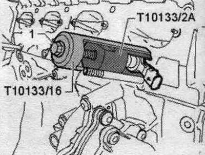
Cover the open intake ports with a clean cloth. Disconnect the plug connector from the injector that needs to be removed. Insert the "T10133/2A" puller into the injector groove. Install the puller "T10133/16" and remove the injector by turning the bolt. The combustion chamber seal must be replaced before reinstalling the injector.
Lambda probes
1. Lambda probe after catalytic converter "G130" and heating element of lambda probe 1 after catalytic converter "Z29"; 2. Lambda probe "G39" and lambda probe heating element "Z19"; Tightening torque: 55 Nm.
Electrical connections of lambda probes (CDNB, CDNC, SAEV, CDZA, SAEA, CADA)
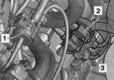
1. Electromagnetic valve 1 of the activated carbon absorber "N80"; 2. Lambda probe after catalytic converter "G130" and heating element of lambda probe 1 after catalytic converter "Z29"; 3. Lambda probe "G39" and lambda probe heating element "Z19".
CFKA and CPMA
Electrical connector of the lambda probe "G39"
6. Lambda probe "G39" and lambda probe heating element "Z19".
Node and plug connectors
1. Electromagnetic valve 1 of the activated carbon absorber "N80"; 2. Lambda probe after catalytic converter "G130" and heating element of lambda probe 1 after catalytic converter "Z29".
New lambda probes are lubricated with mounting paste; avoid getting the paste on the grooves of the lambda probe housing. If using a used lambda probe, lubricate only the threads with heat-resistant paste. Avoid getting any paste on the grooves of the lambda probe housing. The lambda probe wiring must be secured in its original locations to prevent it from coming into contact with the exhaust pipe.