Repair Chevrolet Repair Toyota Repair Honda Repair AvtoVAZ Repair Mercedes-Benz Repair BMW Repair Opel
Home  |  Contacts  |  Sitemap  |    
English Русский
Български
Беларускі
Український
Српски
Hrvatski
Română
Polski
Slovenský
Magyar
AudiManual.ru


  • AUDI 80
  • AUDI 100
  • AUDI A3
  • AUDI A4
  • AUDI A6
  • AUDI A8
  • AUDI Q
  • OTHER
  • ARTICLES
B8 (2007-2015) B7 (2004-2008) B6 (2000-2006) B6 (2000-2006, petrol) B5 (1994-2001) B5 (1994-2001, petrol)

Intake manifold (CDNB, CDNC, SAEV, CDZA, SAEA, CADA) — removal and installation (Audi A4 B8)

  • Home
  • Audi A4
  • B8 (2007-2015)
  • Power unit
  • Petrol engines 1.8/2.0 l
  • Intake manifold (CDNB, CDNC, SAEV, CDZA, SAEA, CADA) — removal and installation
            0
Table of contents: Intake manifold (CDNB, CDNC, SAEV,… ↓ Fuel rail ↓ Removal and installation the intake… ↓ Removal and installation the fuel… ↓

Intake manifold (CDNB, CDNC, SAEV, CDZA, SAEA, CADA)


1. Intake air temperature sensor bolt «G42»: 9 Nm.

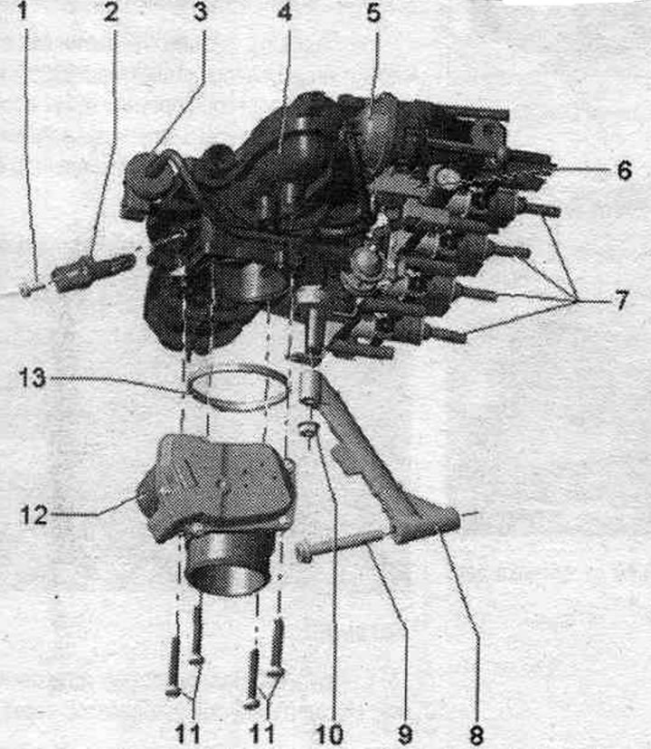
1. Intake air temperature sensor bolt "G42": 9 Nm.
2. Intake air temperature sensor "G42".
3. Electromagnetic valve 1 of the activated carbon absorber "N80": with double check valve.
4. Intake manifold: tighten to a torque of 9 Nm.
5. Vacuum reservoir for charge air regulating flaps (intake manifold regulating flaps).
6. Intake manifold flap valve "N316".
7. Injectors: replace the seal. and Teflon rings, take into account the installation. position.
8. Intake manifold support.
9. Intake manifold pipe bolt: 23 Nm.
10. Fastening nut for intake manifold pipe: 10 Nm.
11. Throttle body bolts "J338": 10 Nm.
12. Throttle valve control unit "J338", throttle valve drive "G186", throttle valve drive angle sensor 1 "G187" and throttle valve drive angle sensor 2 "G188"; after replacing the throttle control module "J338", it must be re-aligned with the engine control unit "J623", use the Tester for this.
13. Lip seal: replace.


Fuel rail


1. Nozzle; always replace together with the combustion chamber seal (Teflon seal. ring); replace…

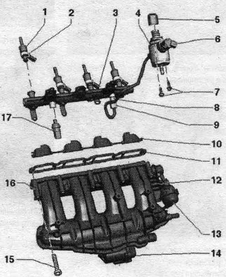
1. Nozzle; always replace together with the combustion chamber seal (Teflon seal. ring); replace the seal. rings, take into account installation. position.
2. Support ring.
3. Fuel rail.
4. High pressure pump: with fuel pressure regulating valve "N276"; there is an electric heater in the fuel tank. fuel pump, which supplies fuel to the mechanics. high pressure pump: when installing a high pressure pump, it is necessary to ensure that the fuel. no dirt got into the system; before installing the high pressure fuel pump. the system should not be under pressure, relieve the pressure; install fuel lines without distortions.
5. Roller pusher.
6. Fuel pressure regulator "N276".
7. High pressure pump bolts: tighten crosswise to 5 Nm and then tighten to 20 Nm.
8. Fuel supply nipple. highways to fuel. ramp: replace, 40 Nm.
9. Fuel supply union nut. highway: 20 Nm.
10. Compression valves (intake manifold flaps).
11. Gasket: replace.
12. Intake manifold.
13. Vacuum reservoir for charge air regulating flaps.
14. Throttle control unit "J338", throttle actuator "G186", throttle actuator angle sensor 1 "G187" and throttle actuator angle sensor 2 "G188": after removing and installing, or replacing the throttle control unit "J338", it is necessary to re-adapt it to the engine control unit "J623", use the tester for this; 7 Nm.
15. Intake manifold bolts: 9 Nm.
16. Intake manifold flap potentiometer "G336": after each removal and installation or replacement of the intake manifold flap potentiometer "G336" or the intake manifold, it is necessary to adapt the intake manifold flap potentiometer "G336" to the engine control unit "J623"; to do this, use the Tester in the "Guided Functions" mode.
17. Fuel pressure sensor "G247": 27 Nm; lubricate the threads with clean oil; always replace the nipple and tighten to 40 Nm.


Removal and installation the intake manifold


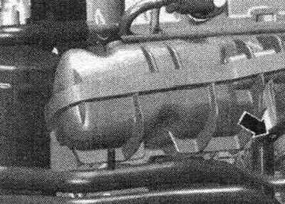
When removing or replacing fuel. to re-adapt the intake manifold valve potentiometer "G336" to the engine control unit "J623," use a tester. To access the injectors, remove the intake manifold and fuel rail. rail. Be sure to replace the combustion chamber seal (Teflon) and the sealing ring. The fuel in the fuel system is under pressure! Disconnect the (-) terminal from the battery. Remove the engine cover. Disconnect the vacuum line "arrow" to the activated carbon absorber. Disconnect the following connectors.

1. Electromagnetic valve 1 of the activated carbon absorber «N80»; 2. Knock sensor 1 «G61»; 3. From…

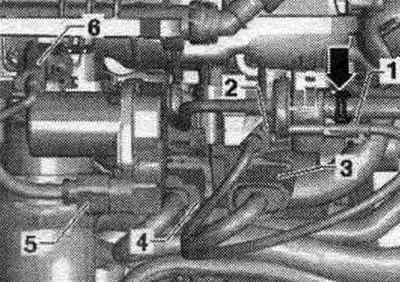
1. Electromagnetic valve 1 of the activated carbon absorber "N80"; 2. Knock sensor 1 "G61"; 3. From the intake manifold flap valve "N316", fuel pressure sensor "G247" and Hall sensor "G40"; 4. From the injectors; 5. Throttle control unit "J338"; 6. Intake air temperature sensor "G42".


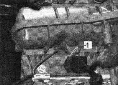
Disconnect connector "1" from Hall sensor "G40".

Disconnect connector «1» from Hall sensor «G40».


Open the clamp "arrow" of the air duct hose and disconnect the hose from the throttle valve module "J338" downwards.


Open the clamp «arrow» of the air duct hose and disconnect the hose from the throttle valve module…


Disconnect the vacuum line "1" at the disconnect point "2". Disconnect the system hose. crankcase ventilation "3".

Disconnect the vacuum line «1» at the disconnect point «2». Disconnect the system hose. crankcase…


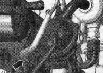
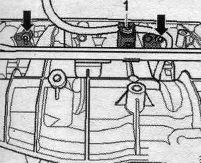
Open the spring clamp -upper arrow- and pull off the fuel supply hose. hose with fuel injection pump. Open the fuel union nut. high-pressure lines - lower arrow - on the fuel injection pump. The fuel system should not be under pressure. Place a clean rag under the leaking fuel. Close open fittings with clean plugs, making sure that no contaminants get into the fuel. syst..

Open the spring clamp -upper arrow- and pull off the fuel supply hose. hose with fuel injection…


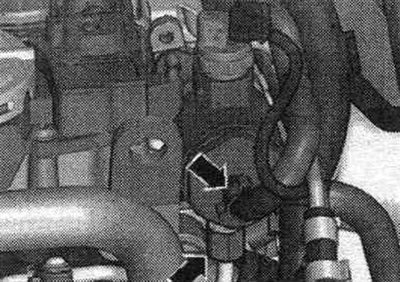
Remove the vacuum line "arrow" from the intake manifold throttle valve "N316".


Remove the vacuum line «arrow» from the intake manifold throttle valve «N316».


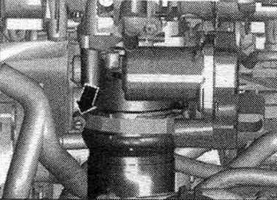
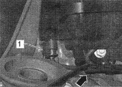
Unscrew the bolt "arrow" of the coolant line from the intake manifold.

Unscrew the bolt «arrow» of the coolant line from the intake manifold.


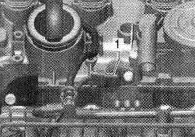
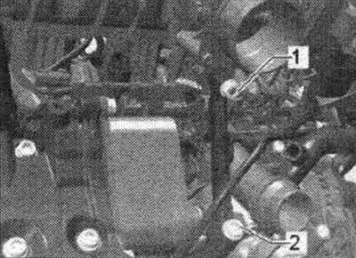
Disconnect the electrical connector from the fuel pressure sensor "G247" "1".

Disconnect the electrical connector from the fuel pressure sensor «G247» «1».


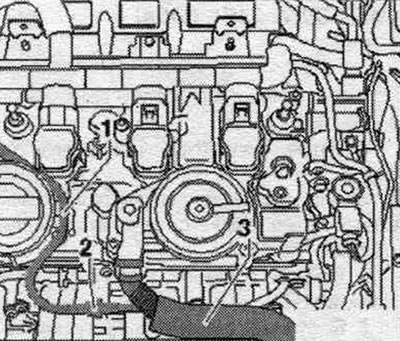
Slightly loosen the fastening nut "1" and completely unscrew the bolt "2".

Slightly loosen the fastening nut «1» and completely unscrew the bolt «2».


Disconnect the oil filter using the Hazel tension band "2171-1" or the oil filter wrench "3417" and remove the oil filter. Unscrew the bolts from the intake manifold using the T10347 wrench. To remove inaccessible bolts without the "T10347" socket, remove the "J338" throttle control module. Carefully lift the intake manifold off the fuel tank. ramp with cylinder head.


Disconnect the oil filter using the Hazel tension band «2171-1» or the oil filter wrench «3417» and…


Disconnect connector "1" of the intake manifold throttle valve potentiometer "G336" and remove the intake manifold. The injectors may remain in the fuel. ramp. Cover the intake ports with a clean rag. Separate the intake manifold from the fuel. ramps.

Disconnect connector «1» of the intake manifold throttle valve potentiometer «G336» and remove the…


Install


Ensure that the injectors are installed correctly. Place the intake manifold through the mounting pins (left and right below) onto the cylinder head. Installation is in reverse order.

Removal and installation the fuel distributor


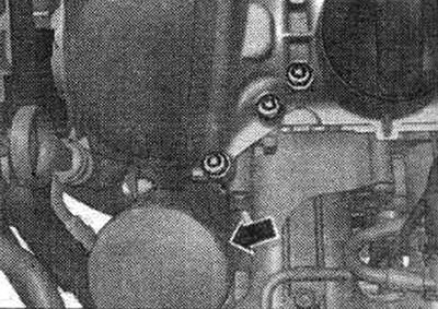
When removing or replacing fuel. the intake manifold valve potentiometer "G336" must be re-adapted to the engine control unit "J623". The intake manifold must be removed. Remove clamp "1". Remove the activated carbon absorber hoses. Disconnect the fuel line from the fuel tank. fuel rail. Unscrew both "arrow" bolts from the fuel rail. Remove the fuel rail from the intake manifold.


When removing or replacing fuel. the intake manifold valve potentiometer «G336» must be re-adapted…


Install


Always replace both fuel supply line fittings. Secure the fuel. highway. Connect the connector. Install the intake manifold. Installation in reverse order.
The article was checked by auto expert Timur Bazhenov
This article is available at russian, bulgarian, belarusian, ukrainian, serbian, croatian, romanian, polish, slovak, hungarian

Share information:
Previous articles
Audi A4 B8: Petrol engines 1.8/2.0 l
Next articles

Air filter — removal and installation
Fuel injection system
Turbocharger — removal and installation
Engine cooling system
Intake manifold (CFKA, SRMA) — removal and installation
High-pressure pump, injectors and lambda probes — removal and…
Exhaust system (EG) — removal and installation
Ignition system — removal and installation of components


Similar articles on other Audi car models:
Intake manifold — removal and installation Audi 80 B3 (1986-1991, petrol)
Intake manifold — removal and installation Audi 100 C3 (1982-1990, diesel)
Removal and installation the lower engine compartment cover Audi A3 Type 8L (1996-2003)
Intake manifold — removal and installation Audi A6 C5 Allroad (1999-2005)
Removal and installation the engine Audi A8 D2 (1994-2002)
Removal and installation of the intake manifold and its… Audi Q7 Typ 4L (2005-2015, diesel)
Removal and installation the intake manifold Audi A2 (1999-2005)
Link to this page in different formats


Visitor comments

No comments yet


How much will 14 + 38 =


A4(B8, 2007-2015) 
  • General information
  • Operating instructions
  • Power unit
  • Petrol engines 1.8 l
  • Petrol engines 1.8/2.0 l
  • Petrol engines 3.0 l
  • Petrol engines 3.2 l
  • Fuel system (petrol)
  • Diesel engines 2.0 l (CA*)
  • Diesel engines 2.0 l (CJCB)
  • Diesel engines 2.7/3.0 l
  • Diesel engines 3.0 l
  • Fuel system (diesel)
  • Transmission
  • Manual gearbox 0B1
  • Manual gearbox 0B2
  • Manual gearbox 0B3
  • Manual gearbox 0B4
  • Automatic transmission 0B5
  • Automatic transmission 0B6
  • Automatic transmission 0AW
  • All-wheel drive system
  • Chassis
  • Front suspension
  • Rear suspension
  • Brake system
  • Steering system
  • Body
  • Exterior
  • Interior
  • Seats
  • Doors, locks and windows
  • Security system
  • Heating and air conditioning
  • Electrical equipment
  • Audio system
  • Power devices
  • Equipment and devices
  • Lighting and lamps
  • Electrical circuits
 
A4(B7, 2004-2008) 
  • General information
  • Introduction to manual
  • Troubleshooting
  • Operating instructions
  • Maintenance
  • Power unit
  • Petrol engines 2.0 (ALT)
  • Petrol engines 2.0 (TFSI)
  • Petrol engines 1.8 (MPI)
  • Diesel engines
  • Cooling system
  • Air conditioner
  • Fuel and exhaust system
  • Ignition system
  • Starting and charging
  • Transmission
  • Clutch
  • Manual gearbox
  • Automatic gearbox
  • Drive shafts
  • Chassis
  • Brake system
  • Front suspension
  • Rear suspension
  • Steering
  • Body
  • Exterior
  • Interior
  • Electrical equipment
  • Equipment and devices
  • Lighting and signaling
  • Windscreen wipers and washers
  • Electrical diagrams
  • Electrical diagrams (since 2007)
 
A4(B6, 2000-2006) 
  • General information
  • Vehicle Description
  • User manual
  • Maintenance
  • Power unit
  • Gasoline engine
  • Diesel engine
  • Lubrication system
  • Cooling system
  • Supply system
  • Injection system
  • Exhaust system
  • Ignition and control
  • Transmission
  • Gear box
  • Clutch and drive shafts
  • Chassis
  • Brake system
  • Car suspension
  • Steering
  • Body
  • Heating and ventilation
  • Exterior (external elements)
  • Interior (internal elements)
  • Electrical equipment
  • Power devices
  • Lighting and appliances
  • Electrical circuits
 
A4(B6, 2000-2006, petrol) 
  • General information
  • Introduction to the guide
  • Car care
  • Power unit
  • Engine repair
  • Lubrication system
  • Cooling system
  • Injection and control system
  • Ignition system
  • Power and exhaust system
  • Transmission
  • Clutch and drive shafts
  • Car gearbox
  • Chassis
  • Suspension and wheels
  • Steering
  • Brake system
  • Body
  • Interior
  • Exterior
  • Electrical equipment
  • Equipment and devices
  • Lighting and signaling
  • Power devices
  • Electrical circuits
 
A4(B5, 1994-2001) 
  • General information
  • Introduction to the guide
  • Car care
  • Maintenance (gasoline)
  • Maintenance (diesel)
  • Power unit
  • Gasoline engines
  • Diesel engines
  • Engine overhaul
  • Cooling system
  • Fuel injection (gasoline)
  • Fuel system (diesel)
  • Exhaust system
  • Ignition system
  • Transmission
  • Clutch
  • Mechanical gearbox
  • Automatic gearbox
  • Drive shafts
  • Chassis
  • Brake system
  • Car suspension
  • Steering
  • Body
  • Exterior
  • Interior
  • Doors, locks and windows
  • Heating and ventilation
  • Electrical equipment
  • Power devices
  • Equipment and devices
  • Electrical circuits
 
A4(B5, 1994-2001, petrol) 
  • General information
  • Vehicle description
  • Maintenance
  • Power unit
  • Engine repair
  • Turbocharging
  • Exhaust system
  • Cooling system
  • Ignition system
  • Fuel system
  • Motronic injection system
  • MPI and MPFI injection system
  • Transmission
  • Clutch
  • Gearbox and shafts
  • Chassis
  • Steering
  • Car suspension
  • Brake system
  • Wheels and tires
  • Body
  • Heating and ventilation
  • Body parts
  • Electrical equipment
  • Fuses and relays
  • Power devices
  • Lighting and lamps
  • Tools and devices
  • Electrical circuits
 
AudiManual.ru © 2017-2026 · Mobile version · Feedback · Sitemap: EN BG BY UA RS HR RO PL SK HU · Site search · News and articles
80 B2 · 80 B3 petrol · 80 B3 · 80 B4 · 100 C3 diesel · 100 C3 petrol · 100 C3 · 100 C4 petrol · 100 C4 · A3 Type 8L · A4 B5 petrol · A4 B5 · A4 B6 petrol · A4 B6 · A4 B7 · A4 B8 · A6 C4 · A6 C5 · A6 C5 Allroad · A8 D2 · Q5 Type 8R · Q7 Typ 4L · Audi A2 ·
This site uses cookies 🍪. Click the button to accept this fact.