
Table of contents: Part I ↓ Mounting position of the charge air… ↓ Part II ↓ Part III ↓ Turbocharger - sequence, tightening ↓ Part IV ↓ Removal and installation a… ↓ Removal and installation the… ↓ Charge air cooling system ↓ Removal and installation the charge… ↓ Removal and installation of the… ↓
Note: All hose connections must be secured with standard hose clamps appropriate for the model year. Hoses and hose fittings syst. air boosters must be cleaned of oils and grease before installation. Only with nipple connections sealed. the ring and sealing surface must be lightly moistened with oil. The supercharging system must be sealed. Self-locking nuts must be replaced. To install the spring band clamps, we recommend using the VAS 6362 or VAG 1921 pliers. Fill the turbocharger with oil through the oil supply line connection. After installing the turbocharger, leave the engine running at idle speed (do not increase the speed) for 1 minute to ensure oil is supplied to the turbocharger.
Part I
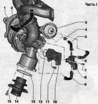
1. Turbocharger: may only be replaced as a set with the exhaust manifold and aneroid box. 2. Hose. 3. Turbocharger aneroid box: can only be replaced with the turbocharger. 4. Hose clamp. 5/6. Hose. 7. Bolt: 3 Nm. 8. Solenoid valve for boost pressure control "N75". 9. Hose. 10. Turbocharger bypass valve "N249": observe installation. position. 11. Bolt: 7 Nm. 12/13. Sealing ring: replace. 14. Fitting. 15. Bolt: 9 Nm.
Mounting position of the charge air recirculation valve "N249"
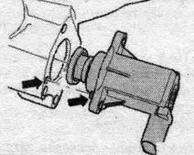
Take into account the installation. position of the "arrow".
Part II
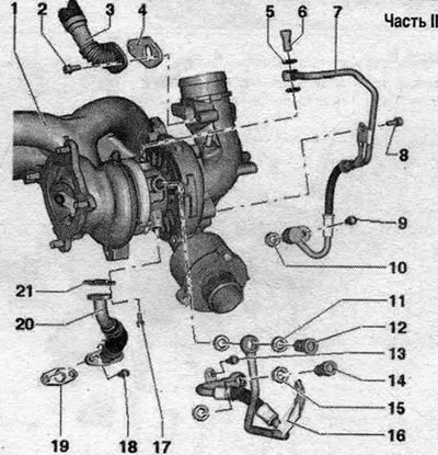
1. Turbocharger. 2. Bolt; 9 Nm. 3. Engine crankcase ventilation line. 4. Gasket: replace. 5. Sealing cuff: replace. 6. Bolt: 30 Nm. 7. Oil supply line. 8/9. Bolt: 9 Nm. 10. Sealing ring: replace. 11. Sealing sleeve: replace. 12. Bolt: 35 Nm. 13. Bolt: 9 Nm. 14. Bolt: 35 Nm. 15. Sealing sleeve: replace. 16. Coolant supply line. 17/18. Bolt: 9 Nm. 19. Gasket: replace. 20. Oil return line. 21. Gasket: replace.
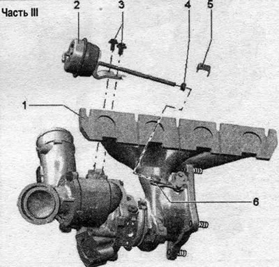
Part III
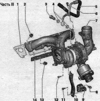
1. Gasket: replace. 2. Nut: replace; lubricate the exhaust manifold mounting pins with heat-resistant paste. 3. Bolt: 35 Nm. 4. Seal: replace. 5. Coolant return line. 6. Bolt: 9 Nm. 7. Turbocharger. 8. Bolt: 30 Nm. 9. Holder. 10. Support. 11. Bolt: 30 Nm. 12. Bolt: 30 Nm; lubricate the bolt with heat-resistant paste. 13. Nut: Do not unscrew to remove the turbocharger, replace; 30 Nm; lubricate the exhaust manifold mounting pins with heat-resistant paste. 14. Clamping bar.
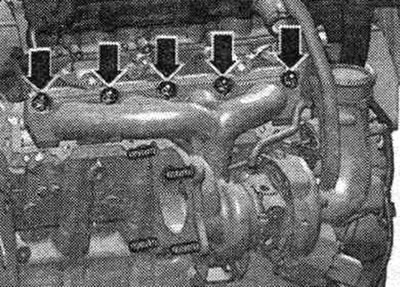
Turbocharger - sequence, tightening
Tighten bolts "1...5" in 4 stages as follows.
1. Tighten the bolts to 5 Nm; 2. Tighten the bolts to a torque of 12 Nm; 3. Tighten the bolts to a torque of 16 Nm; 4. Tighten the bolts to 25 Nm.
Part IV
1. Turbocharger. 2. Turbocharger aneroid box: check. 3. Bolt: 10 Nm. 4. Nut: 9 Nm; protect with sealing wax. 5. Lock washer: replace. 6. Knurled nut.
Other tightening torques (Nm)
| Right air duct to the oil pan | 10 |
| Air duct on the holder | 10 |
Removal and installation a turbocharger
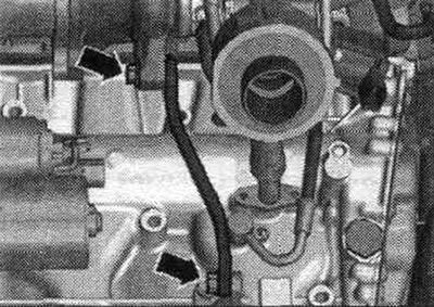
Remove the engine cover "arrows". Drain the coolant. Remove the front exhaust pipe/front muffler. Disconnect connector "1" of air flow meter "G70". Release air intake pipe "2". Remove air flow meter housing. filter up "arrows".

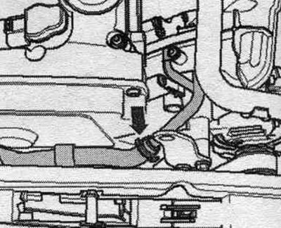
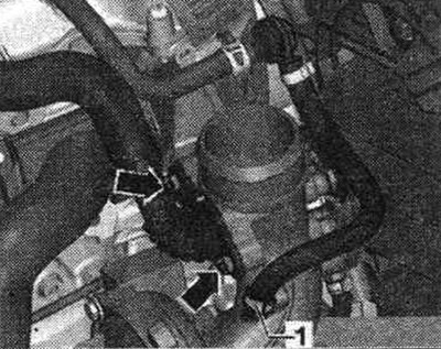
Disconnect the coolant hose "arrow". For better visualization, the installation position is shown with the engine removed.
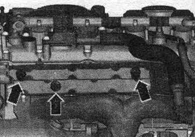
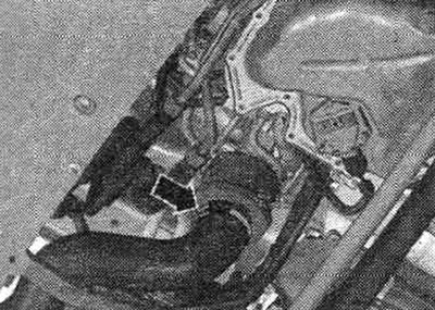
Remove the heat-insulating shield "arrows".
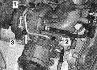
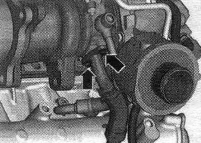
Disconnect the system. crankcase ventilation of the "arrow" engine from the turbocharger. Disconnect hose "1" from the turbocharger.
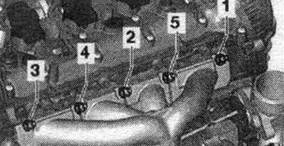
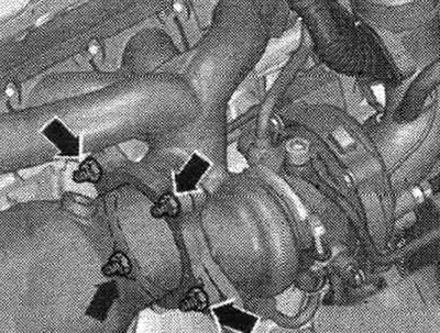
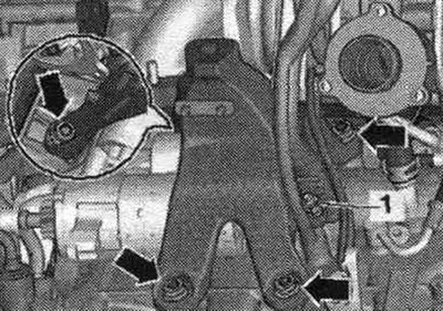
Unscrew bolts "1 and 2" and put the oil supply line aside. Unscrew bolt "3" and move the coolant line to the side.
Disconnect the hose clamp "arrow", remove the air duct hose and set it aside.
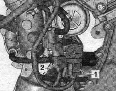
Disconnect connectors "1 and 2" and release the wire.
Unscrew the arrow bolts and remove the turbocharger support.
Unscrew the bolts "arrow" of the oil drain pipe.
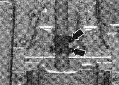
Risk of damage to the disconnecting components in the front muffler. Do not tilt the release components in the front muffler more than 10 degrees. Loosen the bolted connections "arrows" and move the clamping sleeve back.
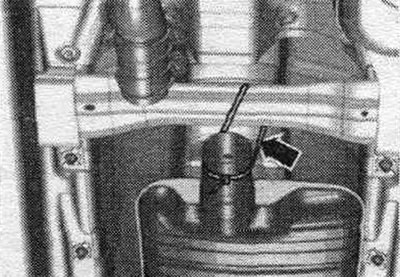
Lower the front muffler a little and tie it to the crossbar "arrow".
Unscrew the arrow nuts and press the catalytic converter back. Remove the right engine mount.
Disconnect electrical wire "1" from the right engine support. Remove the right engine support "arrows".
Unscrew the "arrow" nuts. Remove the turbocharger with the exhaust manifold upward.
Installation
Installation in reverse order. Replace the seal. gasket rings, O-rings and self-locking nuts. Fill the turbocharger with oil through the oil supply line nipple. Hoses and hose fittings syst. air boosters must be cleaned of oils and grease before installation. Secure all hose connections with hose clamps of the appropriate series. Install the right engine mount. Install the catalytic converter. Install the exhaust system. install air ducts with a nipple coupling without stress. Fill with coolant. Check the oil level. After installing the turbocharger, let the engine idle (do not increase the speed) for 1 minute to ensure oil is supplied to the turbocharger.
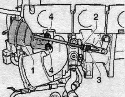
Removal and installation the turbocharger vacuum block
Remove the turbocharger. Remove the locking plate "1" through the turbocharger rod.
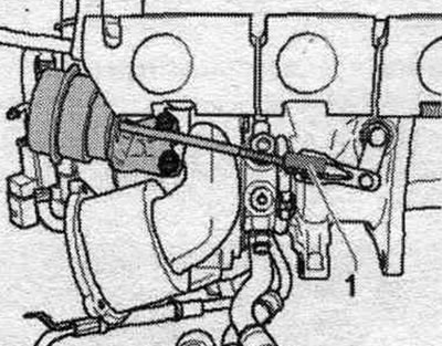
Loosen lock nut "2". Separate the lever from the turbocharger "3". Unscrew vacuum block "1" "4" and remove.
Installation
Installation in reverse order. Adjust the turbocharger vacuum block. Install the turbocharger.
Charge air cooling system
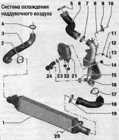
1. Intercooler. 2. Hose clamp: reinforced, 5.5 Nm. 3. Air duct hose: to turbocharger: must be cleaned of oil and grease before installation. 4/5. Hose clamp: reinforced, 5.5 Nm. 6. Air duct hose: to the intake manifold; before installation, clean from oil and grease. 7. Hose clamp: reinforced, 5.5 Nm. 8. Sealing ring: replace. 9. Boost pressure sensor "G31". 10. Bolt: 5 Nm. 11. Rubber tip. 12. Bushing. 13. Nut: 9 Nm. 14. Rubber tip. 15. Hose clamp: reinforced, 5.5 Nm. 16. Air guide tube. 17. Hose clamp: reinforced, 5.5 Nm. 18. Air duct hose: from intercooler; before installation, clean from oil and grease. 19. Hose clamp: reinforced, 5.5 Nm. 20. Bolt: 7 Nm. 21. Resonator. 22. Rubber tip. 23. Hose clamp: reinforced, 5.5 Nm. 24. Air duct hose: to the resonator; before installation, clean from oil and grease.
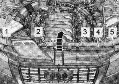
Removal and installation the charge air radiator
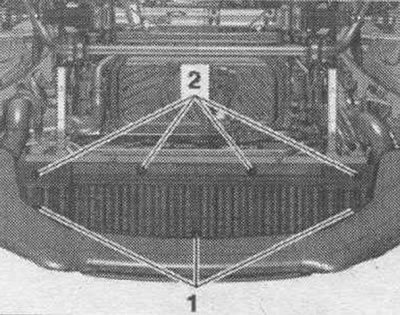
Unscrew the bolts "1, 2, 3, 5", Remove cover "4" of the radiator frame and hang it on the radiator grille "arrow".
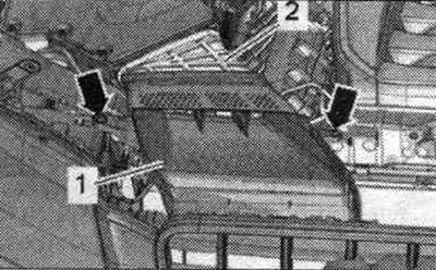
Unscrew the "arrow" bolts. Remove the air duct "1" from the intermediate flange "2" of the air duct housing. filter.
Loosen bolts "1" and "2" and the soundproofing screen of the bumper cover in the rear direction.
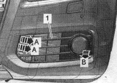
Unlock the retaining clips "arrows A" and remove the air intake grille "1" on the left and right from the lower part of the bumper trim "arrow B". For better visualization, the installation position is shown with the engine removed.
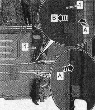
Unlock the fastening brackets "arrow A" and move the air duct "1" to the left and right towards the center of the car "arrow B".
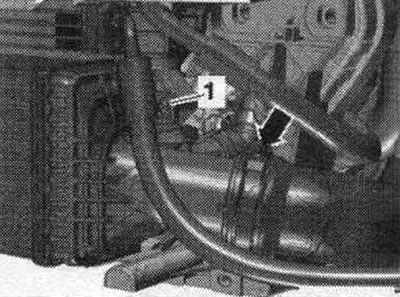
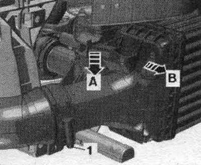
Remove the air duct hose from the intercooler by loosening the hose clamp "arrow". Unscrew the bolt "1".
Remove the air duct hose from the intercooler by loosening the hose clamp "1". Press the clamp down "arrow A" and slightly tilt the top of the intercooler "in the direction of arrow B".
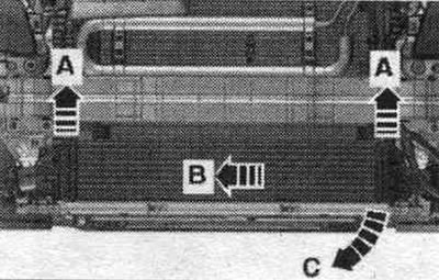
Remove the intercooler from the radiator upwards "arrows A" and push it "in the direction of arrow B". Grasping from the left side, remove the intercooler downwards "arrow C".
Installation
Installation, in reverse order. Hoses and hose fittings syst. air boosters must be cleaned of oils and grease before installation. Secure all hose connections with hose clamps of the appropriate series, and treat the threaded connections of already used clamps with a rust remover.
Removal and installation of the charge pressure sensor "G31"
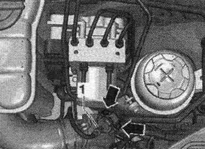
Disconnect plug connector "1" of boost pressure sensor "G31", loosen bolts "arrows" and disconnect boost pressure sensor "G31" from the air duct tube.
Installation
Installation in reverse order. Replace the seal. o-ring.