
Table of contents: Air parts and assemblies. filter ↓ Removal and installation the… ↓ Removal and installation the air… ↓ Remove the air casing. filter ↓
Air parts and assemblies. filter
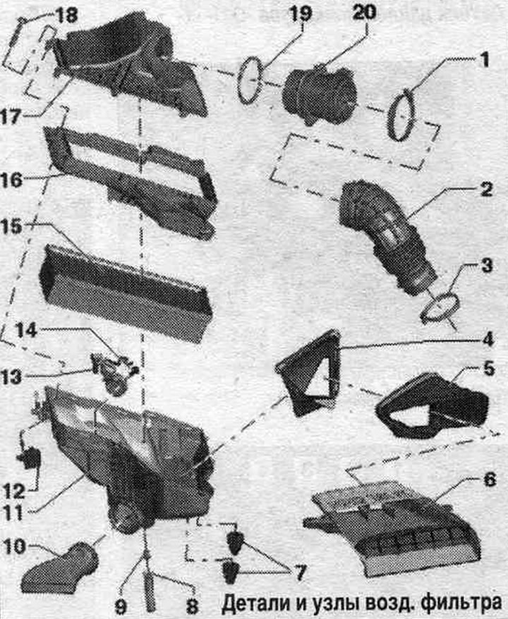
1. Hose clamp.
2. Air duct hose.
3. Hose clamp.
4. Air duct: fixed in the air duct housing. filters, clean the air duct from dirt and leaves.
5. Air duct: clean the air duct from dirt and leaves.
6. Air duct: tighten to the lock frame with a torque of 2 Nm, clean the air duct from dirt and leaves.
7. Rubber bushing.
8. Water drain hose: Clean the water drain hose from dirt and leaves (important).
9. Water drainage hose guide.
10. Heated air supply line (only in countries with cold climates): Insert the heated air supply line into the air filter until it stops and turn it clockwise until it clicks.
11. Lower part of the air. filter: Clean the lower part of the air filter. filters from salt deposits, dirt and leaves; check the drain for contamination and clean if necessary (important).
12. Fastening for the lower part of the air. filter: fix (with a clear feeling); do not use lubricants.
13. Intake air changeover valve "N335": parts (bypass flap with intake air changeover valve "N335") are not installed in all trim levels and not for all countries.
14. Bolt: Only if the air inlet changeover valve "N335" is installed.
15. Replaceable air element. filter: always use the original filter element and also clean the fine filter (if installed).
16. Nozzle for the lower part of the air. filter.
17. Upper part of the air. filters: Clean the top of the air filter. filters from salt deposits, dirt and leaves.
18. Bolt.
19. Sealing ring: replace if damaged.
20. Air flow meter.
Removal and installation the motorcycle cover. compartment
Carefully remove the engine cover from the mounting bolts. Do not remove the engine cover by jerking or moving it to the side.
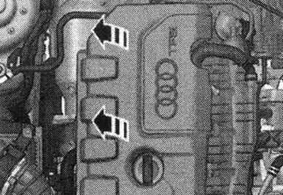
Install: To avoid damaging the engine cover, do not hit it with your fists or tools. Install the engine cover (pay attention to the oil filler pipe and dipstick to determine the oil level) on the engine. Press the engine protective cover into the rubber tips with both hands.
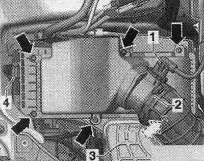
Removal and installation the air liner. filter
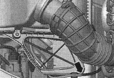
Disconnect plug connection "1" from the air flow meter "G70". Open clamp "2" of the air duct leading to the turbocharger and remove the hose from the air flow meter "G70". Unscrew all the "arrow" bolts from the top of the air flow meter. filter and remove it in an upward direction. Remove the old air filter element. filter.
Installation
To ensure the G70 air flow meter functions properly, it is essential to follow these instructions and steps. If the air filter element is heavily soiled or saturated with moisture. filters, dirt particles or moisture can get into the G70 air flow meter and distort the data obtained. This causes a lack of power due to the reduction in the calculated amount of fuel injected. Use only the original filter element. Hoses and hose fittings syst. air boosters must be cleaned of oils and grease before installation. Do not use silicone-containing lubricants during installation. The air filter housing must be clean. Secure all hose connections with clamps of the appropriate series. When blowing through the air housing. when changing filters, please note the following: to avoid malfunctions, it is necessary to clean the engine air intake components with a rag, such as the air flow meter, intake manifold, etc. Blow out the "arrow" drain at the bottom of the air filter with compressed air. filters. Items 1, 2 and 3 are not taken into account.
Clean the air duct housing. filter (upper and lower parts) from deposits of salt, dirt or leaves (if necessary, using a vacuum cleaner). Check the air flow meter and air duct hose (side of clean air) for the absence of salt residue, dirt and leaves. Check for dirt and leaves in the air duct from the front closing panel of the body to the air housing. filter. If present, connect a vacuum hose to the air inlet changeover valve "N335". When installing the filter element, ensure that it is centered at the bottom of the air intake. filter. Carefully, without applying much force, install the upper part of the air filter. filters to the bottom. At the same time, make sure that the upper part of the air. the filter was not installed crookedly (monitor the working edge of the filter insert seal). Check the tightness of the air supply hose on the G70 air flow meter. Install in reverse order.
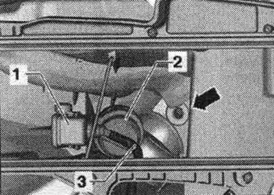
Remove the air casing. filter
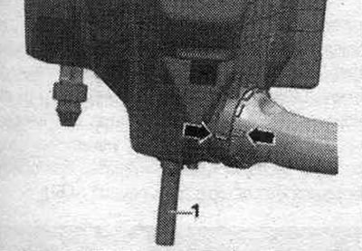
Disconnect plug connection "1" from the air flow meter "G70". Open clamp "2" of the air duct leading to the turbocharger and remove the hose from the air flow meter "G70". Remove air duct "3". Remove the vacuum line "arrow" (if available).
Unlock the "4" fastening of the lower part of the air. filter (press the rubber parts on the right and left and remove them upwards). The parts (bypass valve with air inlet changeover valve "N335" "1") are not installed in all trim levels and not for all countries. When installing the fastener, do not use lubricants. Disconnect the connector of the air intake switching valve "N335" (if available). Carefully remove the air duct housing. filter.
Install
To ensure the G70 air flow meter functions properly, it is essential to complete the following steps. Use sealant to install the air intake sleeve (silicone-free). Secure all hose connections with clamps of the appropriate series. If a warm air intake pipe is installed (only in the version for countries with cold climates), ensure that the suction pipe "arrow" is correctly fixed (follow the markings). Check the air flow meter and air duct hose (side of clean air) for the absence of salt residue, dirt and leaves. Check the suction channel up to the filter element for contamination. Connect the connector of the air intake changeover valve "N335" (if available). Reinstall the air casing. filter. The water drain hose should be laid straight down and not be kinked.
Install the vacuum line "arrow" (if available). Check the air supply hose for tightness on the G70 air flow meter. Reconnect the G70 air flow meter connector. Install the air duct. Further installation is carried out in reverse order.