
Removal
1. Disconnect the negative (-) battery cable.
Warning: Follow the instructions in Section Replacing the battery.
2. Remove the engine covers, refer to Section Removal and installation the upper engine cover/lower engine compartment protection/subframe.
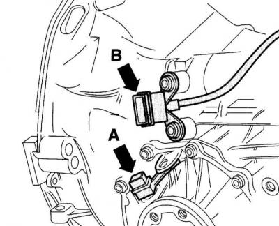
3. Unscrew the turbocharger mounting nuts.
4. Remove all engine/gearbox connecting bolts that are accessible from above.
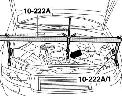
5. Install the crossbar and sling the engine.
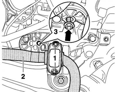
Caution: The fuel supply line is under pressure! Before opening the hose connection, cover it with a thick rag. Then relieve the pressure by carefully disconnecting the hose.
6. Raise and place the vehicle on stands.
7. Models with auxiliary heating: Remove the bolts securing the auxiliary/auxiliary heating outlet pipe to the lower engine compartment cover.
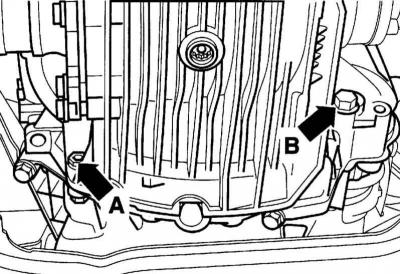
8. Loosen the mounting bolts and remove the lower engine compartment cover holder (arrow).
9. Remove the heat shield over the right drive shaft.
10. Loosen the mounting bolts and remove the left and right covers (arrows) of the exhaust pipe.
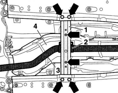
11. Remove the front tunnel cross member (1) (arrows in the accompanying illustration).
12. Remove the intake pipe (3) from the terminal sleeve (2), refer to Part Exhaust and emission control systems. Turbocharger.
13. Remove the heat shield (4) over the exhaust system.
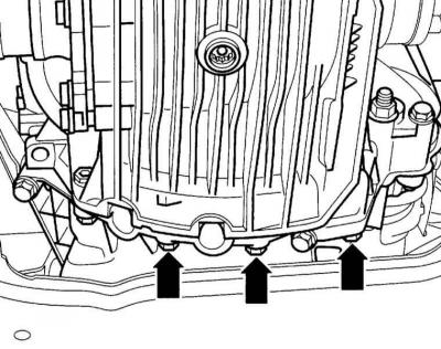
14. Remove the lower engine/gearbox connecting bolts (arrows in the accompanying illustration).
15. Disconnect both drive shafts at the flanges and tie them with wire, refer to Section Removal and installation the drive shaft.
Warning: Be careful not to damage the protective coating on the drive shafts when unscrewing.
16. Remove the starter, but do not disconnect the cable from the starter. Secure the starter to the body with a wire.
17. At the service station, the gearbox is fixed and supported by a VAG lift. If the specified lift is not available, place a garage lift with a wide wooden pad under the gearbox and slightly lift the gearbox.
18. First remove the bolts (2) and then the bolts (3) on the tunnel crossmember. Remove both nuts (4), remove the tunnel crossmember.
19. Carefully lower the lift with the engine/gearbox so that the gearbox is visible. Remove the lift.
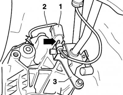
20. Remove the bolt (A) securing the rod to the gearbox and disconnect the shift joint from the axle.
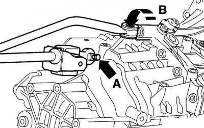
21. Disconnect the push rod by unscrewing the Allen screw (B) at the gearbox.
22. Remove the connector (1), if present, from the holder (arrow on the accompanying illustration). Disconnect the connector and move the cable aside.
23. Disconnect the connector (A) of the tachometer sensor and (B) of the reversing light on the left side of the gearbox.
24. Disconnect the engine speed sensor, if present, on the left side of the gearbox (arrow on the accompanying illustration) and take it aside.
25. Remove the lower engine/gearbox connecting bolts, but not bolts (A) and (B).

26. Place a suitable lift under the gearbox and secure the gearbox with an adjustment plate.
27. Remove the remaining engine/gearbox connecting bolts (A) and (B).
28. Press the gearbox away from the engine and slowly lower it down.
Installation
Caution: When replacing any gearbox-mounted parts or bolts, please note the following: The gearbox housing is made of magnesium or aluminum alloy. The parts installed, such as the cover and bolts, are used accordingly. If aluminum gearbox parts are installed on a magnesium alloy housing, the latter will be subject to corrosion. This also applies to the engine/gearbox flange mounting bolts. They have a special coating for the magnesium alloy gearbox housing. A magnesium alloy gearbox is indicated by the inscription "Mg AL 9 Zn 1" on the bottom of the gearbox and in the area of the oil filler plug.
1. Before installation, check the clutch, refer to Section Removal, installation and checking the clutch.
2. Clean the splined connection of the input shaft and lightly lubricate with MoS 2 AUDI-G000100 grease.
Caution: The driven clutch disc should easily fit onto the gearbox input shaft. Remove excess grease.
3. Clean all threaded holes into which self-locking bolts are screwed with a tap from any remaining sealant. Be sure to replace the self-locking bolts and nuts with new ones.
4. Check the clutch release bearing for wear and replace if necessary. If the plastic bearing has grooves deeper than 0.5 mm, the bearing must be replaced.
5. Lubricate the mating surface of the pushrod at the clutch release bearing lever with copper grease, such as, "Z381 351 TE".
6. Check if the centering bushings for centering the engine/gearbox connection in the cylinder block are in place; if necessary, insert them.
7. Ensure that the intermediate plate on the engine, if any, is correctly positioned.
8. Insert the gearbox horizontally into the clutch. If the gearbox input shaft does not enter the driven disk during installation, turn the shaft by hand by the flange.
9. Install the clutch slave cylinder with the holder. Using a pry bar, insert the cylinder so that the mounting bolt can be easily inserted. Tighten the bolt to the torque25Nm.
10. Reinstall the starter, refer to Section Removal and installation the starter.
11. Screw in the lower bolts (A) for fastening the engine with the gearbox and (B) for fastening the starter.
12. Lower the engine/gearbox assembly.
13. Tighten the upper engine/transmission mounting bolts to the specified torque.
14. Secure the tunnel crossmember to the gearbox support (1).
15. Secure the tunnel cross member to the body. First screw in bolt (2), then bolt (3).
16. Tighten the 3 engine-to-gearbox mounting bolts from below to a torque of 45 Nm.

17. Install the gear shift rod in place. Secure it with a torque of 20 Nm.
18. Install the push rod and tighten it to a torque of 40 Nm.

19. Install the drive shafts and shaft shield, refer to Section Removal and installation the drive shaft.
20. Connect all previously disconnected connectors.
21. When making electrical connections, ensure that all clamps removed or cut during dismantling are installed in their original places.
22. Install the exhaust pipe heat shield. Install the downpipe and install the exhaust system, refer to Section Removal and installation of the exhaust system. Replacement of the central, additional muffler, end pipe.
23. Check the adjustment of the gear shift drive, refer to Section Adjusting the gear shift drive.
24. Check the oil level in the gearbox, refer to Section Checking the oil level in a manual transmission.
25. Connect the negative (-) battery cable.
Warning: Follow the instructions in Section Replacing the battery.
Tightening torques for threaded connections
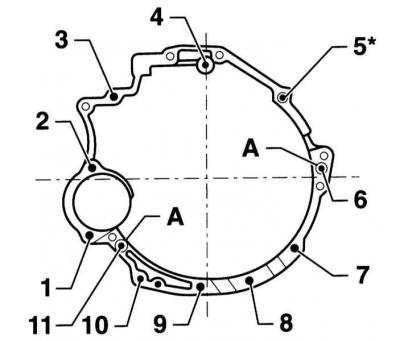
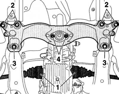
Engine/gearbox mounting bolts. Engines 1.6, 1.8, 1.9, 2.0 l
|
Position |
Bolt |
Moment tightening |
|
Engines 1.6, 2.0 l |
||
|
1, 3, 4 |
M12 x 75 |
65Nm |
|
2 |
M12 x 90 |
65Nm |
|
5, 11 |
M12 x 110 |
65Nm |
|
7-10 |
M10 x 45 |
45Nm |
| 11 | M12 x 130 | 65Nm |
|
A |
Centering bushings | |
|
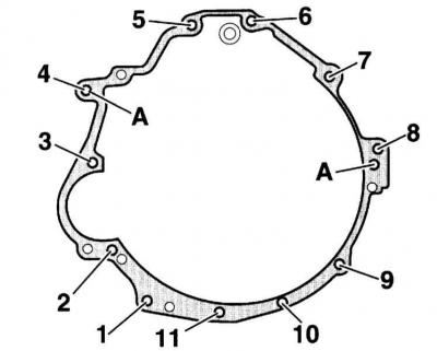
Engines 1.8, 1.9 l: |
||
| 1, 3, 4 | M12 x 67 | 65Nm |
| 2, 6 | M12 x 90 | 65Nm |
| 5, 11 | M12 x 110 | 65Nm |
| 7-11 | M10 x 45 | 45Nm |
|
A |
Centering bushings | |
Engine/gearbox mounting bolts. Engines 2.4, 3.0 l
|
Position |
Bolt |
Tightening torque |
|
Engine 2.4 l |
||
|
1, 9, 10, 11 |
M10 x 45 |
45Nm |
|
2 |
M10 x 135 |
65Nm |
|
3 |
M12 x 130 |
65Nm |
|
4, 5, 6 |
M12 x 67 |
65Nm |
| 7 | M12 x 90 | 65Nm |
| 8 | M12 x 80 | 65Nm |
| A | Centering bushings | |
| Engine 3.0 l | ||
| 1, 9, 10, 11 | M10 x 60 | 45Nm |
| 2 | M10 x 150 | 65Nm |
| 3 | M12 x 130 | 65Nm |
| 4 | M12 x 80 | 65Nm |
| 5, 6, 8 | M12 x 90 | 65Nm |
| 7 | M10 x 100 | 45Nm |
| A | Centering bushings | |
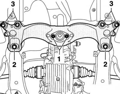
Engine Mount/Stabilizer Bar Mounting Bolts
- 1 — Stabilizer (2) to engine support console 25 Nm
- 3 — Engine support to engine support console 25 Nm
Caution: Nuts (1) must be replaced.
(The article is a reprint of material from «Audimanual.ru»)